
Operating instructions

K3 Series Installation Instructions
14
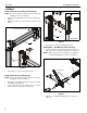
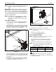
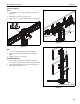
Outside Faceplates (K3G310 and K3G320 only)
1. Remove hex head bolt from bottom of faceplate assembly.
(See Figure 21)
2. Slide out removable plate from bottom of faceplate
assembly. (See Figure 21)
Figure 21
3. Remove faceplate assembly from array arm. (See Figure 21)
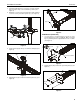
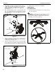
To Reattach Outside Faceplate Assembly (K3G310
and K3G320 only)
NOTE: Be sure the faceplate adjustment knob is on top when
reinstalling the faceplate assembly. (See Figure 22)
NOTE: Faceplate assemblies may be reattached on the fixed
part of the arm. (See Figure 22)
4. Place faceplate assembly on array arm at desired mounting
position. (See Figure 22)
5. Slide removable plate back into slot at bottom of faceplate
assembly. (See Figure 22)
6. Reinstall hex head bolt removed in Step 1 to secure
faceplate assembly to array arm. (See Figure 22)
Figure 22
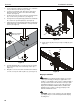
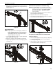
Lateral Shift (On Fixed Arm)
NOTE: The procedure below applies when the outside
faceplates have been attached to the fixed arm. If
outside faceplates are still attached to extension arms,
use the extension arms for lateral shift.
1. Loosen knob on top of outside faceplate assembly until
faceplate can slide freely along array arm. (See Figure 23)
2. Adjust lateral position as desired. (See Figure 23)
3. Tighten knob to secure lateral position. (See Figure 23)
Figure 23
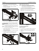
Pitch/Roll/Yaw Adjustment
Outside Faceplates
1. Loosen knob on top of faceplate assembly. (See Figure 24)
2. Adjust pitch, roll and/or yaw as desired. (See Figure 24)
3. Tighten knob to secure desired faceplate position. (See
Figure 24)
Figure 24
removable plate
1
2
3
removable plate
5
6
4
Faceplate
adjustment
knob
2
1
3
1 3
2