
Operating instructions

Installation Instructions K3 Series
13
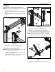
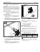
2. When arms are at desired pivot position, lock pivot position
by tightening pivot adjustment screws using 5/16” hex key
(Q). (See Figure 17)
Figure 17
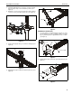
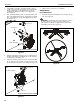
Height Adjustment
NOTE: Height adjustment for center displays should be set
prior to installing display. Due to the location of the
height adjustment screws for the center displays, the
center displays will need to be removed in order to
adjust the height. (See Figure 18)
1. Loosen height adjustment screws for specific display that
will be adjusted. (See Figure 18)
2. Adjust arm or display to desired height. (See Figure 18)
3. Tighten height adjustment screws to lock display’s position.
(See Figure 18)
Figure 18
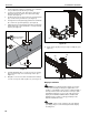
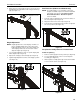
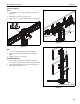
Arm Extension (K3G310 and K3G320 only)
NOTE: For smaller displays or if converting to a 2x1 array,
faceplate assemblies may be removed and reattached
to fixed part of the arm. See Faceplate Assembly
Removal/Reattachment - Outside Faceplates
section for details.
1. Turn arm extension adjustment knob counter-clockwise on
arm to be adjusted. (See Figure 19)
2. Adjust arm extension as desired. (See Figure 19)
3. Turn arm extension adjustment knob clockwise on adjusted
arm to lock position. (See Figure 19)
Figure 19
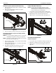
Faceplate Assembly Removal / Reattachment
Center Faceplate(s)
1. Remove column cap (D) from array column. (See Figure 20)
2. Loosen height adjustment screws for center faceplate
assembly. (See Figure 20)
3. Slide faceplate assembly up through column channel until it
is removed from column. (See Figure 20)
Figure 20
pivot adjustment screws
2
2
2
1
3
1
3
2
1
3
2
3
1