
Operating instructions
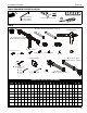


K3 Series Installation Instructions
12
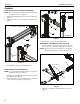
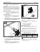
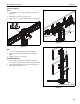
3. Using Phillips screwdriver, carefully install two selected
screws (J or H) through selected spacers (L or M) into the
upper mounting holes on the display. Thread screws
completely into display, then back out 3 complete turns.
(See Figure 14)
4. Pick up and align display so that screws (K) (installed on the
back of the display in the previous step) fit into the mounting
holes on the faceplate. Lower the display firmly into place.
(See Figure 14)
Figure 14
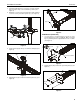
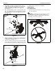
5. Slide two remaining selected spacers (L or M) in between
faceplate and display, positioning them over the lower two
mounting holes. (See Figure 15)
6. Install two remaining selected screws (J or H) through lower
two mounting holes on faceplate, selected spacers (L or M)
into the lower mounting holes on the display. (See Figure 15)
Figure 15
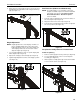
7. Tighten all four screws. Do not overtighten!
Adjustments
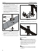
Pivot Adjustment
1. Array arms may pivot toward the front of mount up to 15° per
arm. (See Figure 16)
WARNING: Pivoting array arms toward the back of mount
may cause K3 Series mount to tip over causing serious
personal injury or damage to equipment! Do not pivot arms
toward back of mount! (See Figure 16)
Figure 16
(L or M) x 2
(J or H) x 2
3
Center faceplate
(array stand not shown for clarity)
4
(L or M) x 2
(J or H) x 2
6
Center faceplate
(array stand not shown for clarity)
5
front
front
(top view)
11