
Operating instructions
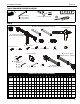


Installation Instructions K3 Series
11
NOTE: Supplied screws (H, J and K) may not fit properly for all
displays. See display’s operating instructions for
details.
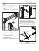
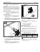
IMPORTANT ! : When applicable, always install center
display FIRST in order to prevent stand from tipping! If
there are no center faceplates (K3F220 and K3G220), be
sure to support opposite arm when mounting displays to
prevent stand from tipping! If possible, mount displays to
both sides simultaneously.
NOTE: Set height of lower center display prior to installing
other displays. See Height Adjustment section for
details. Center of display must be at least 18" above
desk surface.
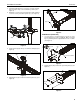
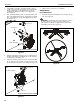
Flush Mounting Holes
1. Position faceplate in desired mounting position. Adjust as
required before proceeding. See Height Adjustment
section for details.
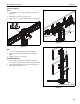
2. Using Phillips screwdriver, carefully install two M4 x 12mm
Phillips pan machine screws (K) into the upper mounting
holes on the display. Thread screws completely into display,
then back out 3 complete turns. (See Figure 12)
Figure 12
3. Pick up and align display so that screws (K) (installed on the
back of the display in the previous step) fit into the mounting
holes on the faceplate. Lower the display firmly into place.
(See Figure 12)
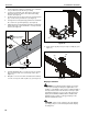
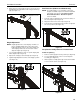
4. Using Phillips screwdriver, install two M4x12 mm Phillips
pan machine screws (K) through the lower mounting holes
on faceplate into the display. (See Figure 13)
Figure 13
5. Tighten all four screws (K). Do not over tighten!
NOTE: If roll adjustment is desired for center faceplate, do not
tighten screws.
6. Repeat Steps 1-5 for other displays.
7. Proceed to Cable Management section.
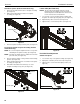
Recessed Mounting Holes
NOTE: If faceplate does not fit into recessed area of display,
proceed with the steps in this section.
1. Determine depth of recessed mounting holes relative to
back surface of display (against which faceplate will
contact).
2. Select proper length spacer and screw from table below:
NOTE: All spacers used should be the same length. If the
recess depths result in multiple spacer lengths, then
select the longer spacer.
CAUTION: Using screws of improper size may damage
your display! Proper screws will easily and completely thread
into display mounting holes.
Center faceplate
(array stand not shown for clarity)
(K) x 2
2
IF recess DEPTH is: THEN use spacer: AND screw:
3/8” or less L (3/8” long) J (M4 x 20mm)
More than 3/8” up to
and including 3/4”
M (3/4” long) H (M4 x 30mm)
Center faceplate
(array stand not shown for clarity)
(K) x 2
4