SD8362E 20x Zoom • 2MP • Full HD • WDR Pro Rev. 1.
VIVOTEK Table of Contents Revision History ��������������������������������������������������������������������������������������������������������������������������������������3 Overview ������������������������������������������������������������������������������������������������������������������������������������������������������4 Read Before Use �������������������������������������������������������������������������������������������������������������������������������������5 Package Contents ��
VIVOTEK Local storage > Content management ��������������������������������������������������������������������������������������������������������������� 110 Appendix ���������������������������������������������������������������������������������������������������������������������������������������������������������������� 112 URL Commands for the Network Camera ���������������������������������������������������������������������������������������������������������� 112 Technical Specifications �����
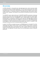
VIVOTEK Overview VIVOTEK SD8362E is a high performance day/night speed dome network cameras suitable for professional outdoor surveillance applications. The IP66-rated housing protects the camera body against rain and dust and the wide temperature range ensures operation under extreme weather conditions. It is especially suitable for monitoring wide open indoor/outdoor spaces such as airports, highways, and parking lots where high-level reliability and precision are always required.
VIVOTEK Read Before Use The use of surveillance devices may be prohibited by law in your country. The Network Camera is not only a high-performance web-ready camera but can also be part of a flexible surveillance system. It is the user’s responsibility to ensure that the operation of such devices is legal before installing this unit for its intended use. It is important to first verify that all contents received are complete according to the Package Contents listed below.
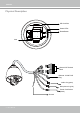
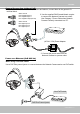
VIVOTEK Physical Description SD Card Slot Status LEDs Reset Button Lens D GN 2DO 1 DO GND DO2DO1DO+ + DO GND D13 D12 D11 GND D13 D12 D11 General I/O Terminal Block Ethernet 10/100 RJ45 Plug Audio Out (green) Microphone In (pink) Power Cord Socket (black) Ground 6 - User's Manual
VIVOTEK Status LED Item LED status Description 1 Steady red Power on and system booting Red LED off Power off 2 Steady red & Green blinking every 1 sec. Network normal (heartbeat) Steady red & Green LED off Network failed 3 Steady red & Green LED blilnking every 2 sec. Audio mute (heartbeat) 4 Red blinking every 0.15 sec. & Green blinking Upgrading firmware every 1 sec. 5 Red blinking every 0.15 sec. & Green blinking Restoring default every 0.15 sec.
VIVOTEK Installation Hardware Installation Mounting the Network Camera 1. Attach the alignment sticker to the wall. 2. Drill four pilot holes into the wall. 3. Attach the smoked dome cover to the Network Camera using the supplied four black screws. 4. Stick the supplied two pieces of silica gel symmetrically to the inner side of the dome cover. Then place the metal ring into the dome cover to fix the silica gel. 5. Fix the dome cover to the Network Camera and secure it by rotating it clockwise. 6.
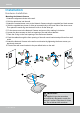
VIVOTEK General Connection (without PoE) 1. If you have external devices such as sensors and alarms, connect them to the general I/O terminal block. GND DO2DO1DO+ GND DI3 DI2 DI1 GND: Ground DO2: Digital Output 2 DO1: Digital Output 1 DO+: Digital Outupt (DC12V) GND: Ground DI3: Digital Input 3 DI2: Digital Input 2 DI1: Digital Input 1 2. Use the supplied RJ45 female/female coupler to connect the Network Camera to a switch. Use Category 5 Cross Cable when Network Camera is directly connected to a PC.
VIVOTEK Network Deployment Setting up the Network Camera over the Internet There are several ways to set up the Network Camera over the Internet. The first way is to set up the Network Camera behind a router. The second way is to utilize a static IP. The third way is to use PPPoE. Internet connection via a router Before setting up the Network Camera over the Internet, make sure you have a router and follow the steps below. 1.
VIVOTEK Internet connection with static IP Choose this connection type if you are required to use a static IP for the Network Camera. Please refer to LAN on page 49 for details. Internet connection via PPPoE (Point-to-Point over Ethernet) Choose this connection type if you are connected to the Internet via a DSL Line. Please refer to PPPoE on page 49 for details.
VIVOTEK Software Installation Installation Wizard 2 (IW2), free-bundled software included on the product CD, helps you set up your Network Camera on the LAN. IW2 1. Install IW2 under the Software Utility directory from the software CD. Double click the IW2 shortcut on your desktop to launch the program. Installation Wizard 2 2. The program will conduct an analysis of your network environment. After your network environment is analyzed, please click Next to continue the program. 3.
VIVOTEK Ready to Use 1. A browser session with the Network Camera should prompt as shown below. 2. You should be able to see live video from your camera. You may also install the 32-channel recording software from the software CD in a deployment consisting of multiple cameras. For its installation details, please refer to its related documents. IMPORTANT! • Currently the Network Camera utilizes 32-bit ActiveX plugin. You CAN NOT open a management/view session with the camera using a 64-bit IE browser.
VIVOTEK Accessing the Network Camera This chapter explains how to access the Network Camera through web browsers, RTSP players, 3GPP-compatible mobile devices, and VIVOTEK recording software. Using Web Browsers Use Installation Wizard 2 (IW2) to access to the Network Cameras on the LAN. If your network environment is not a LAN, follow these steps to access the Netwotk Camera: 1. Launch your web browser (e.g., Microsoft® Internet Explorer, Mozilla Firefox, or Netscape). 2.
VIVOTEK ► By default, the Network Camera is not password-protected. To prevent unauthorized access, it is highly recommended to set a password for the Network Camera. For more information about how to enable password protection, please refer to Security on page 38. ► If you see a dialog box indicating that your security settings prohibit running ActiveX ® Controls, please enable the ActiveX ® Controls for your browser. 1. Choose Tools > Internet Options > Security > Custom Level. 2.
VIVOTEK Using RTSP Players To view the H.264/MPEG-4 streaming media using RTSP players, you can use one of the following players that support RTSP streaming. Quick Time Player Real Player VLCthe media player 1. Launch RTSP player. 2. Choose File > Open mpegable PlayerURL. An URL dialog box will pop up. 3.
VIVOTEK Using 3GPP-compatible Mobile Devices To view the streaming media through 3GPP-compatible mobile devices, make sure the Network Camera can be accessed over the Internet. For more information on how to set up the Network Camera over the Internet, please refer to Setup the Network Camera over the Internet on page 10. To utilize this feature, please check the following settings on your Network Camera: 1.
VIVOTEK Using VIVOTEK Recording Software The product software CD also contains recording software, allowing simultaneous monitoring and video recording for multiple Network Cameras. Please install the recording software; then launch the program to add the Network Camera to the Channel list. For detailed information about how to use the recording software, please refer to the user’s manual of the software or download it from http://www.vivotek.com.
VIVOTEK Main Page This chapter explains the layout of the main page. It is composed of the following sections: VIVOTEK INC. Logo, Host Name, Camera Control Area, Configuration Area, and Live Video Window. VIVOTEK INC. Logo Resize Buttons Host Name Camera Control Area Hide Button Configuration Area Live View Window VIVOTEK INC. Logo Click this logo to visit the VIVOTEK website. Host Name The host name can be customized to fit your needs. For more information, please refer to System on page 27.
VIVOTEK Pan: Click this button to start the auto pan (360° continuous rotation). Stop: Click this button to stop the Auto Pan and Auto Patrol functions. Patrol: Once the Administrator has determined the list of preset positions, click this button to command the camera to patrol among those positions on the Patrol List. The Network Camera will patrol continuously. For more information, please refer to Camera Control on page 65.
VIVOTEK Live Video Window ■ The following window is displayed when the video mode is set to H.264 / MPEG-4: H.264/MPEG-4 Protocol and Media Options Video Title Title and Time Video (TPC-AV) Time 2011/03/10 17:08:56 Video 17:08:56 2011/03/10 Video and Audio Control Buttons Video Title: The video title can be configured. For more information, please refer to Video settings on page 67. H.264 / MPEG-4 Protocol and Media Options: The transmission protocol and media options for H.
VIVOTEK recording stops accordingly. To specify the storage destination and file name, please refer to MP4 Saving Options on page 25 for details. Volume: When the local computer. Mute function is not activated, move the slider bar to adjust the volume on the Mute: Turn off the volume on the local computer. The button becomes the clicking the Mute button. Audio On button after Talk: Click this button to talk to people around the Network Camera.
VIVOTEK Start MP4 Recording: Click this button to record video clips in MP4 file format to your computer. Stop MP4 Recording button to end recording. When you exit the web browser, video Press the recording stops accordingly. To specify the storage destination and file name, please refer to MP4 Saving Options on page 25 for details. Full Screen: Click this button to switch to full screen mode. Press the “Esc” key to switch back to normal mode.
VIVOTEK Client Settings This chapter explains how to select the stream transmission mode and saving options on the local computer. When completed with the settings on this page, click Save on the page bottom to enable the settings. H.264 / MPEG-4 Media Options H.264/MPEG-4 Media Options Select to stream video or audio data or both. This is enabled only when the video mode is set to H.264 or MPEG-4. H.264 / MPEG-4 Protocol Options H.
VIVOTEK MP4 Saving Options Users can record live video as they are watching it by clicking page. Here, you can specify the storage destination and file name. Start MP4 Recording on the main Folder: Specify a storage destination for the recorded video files. File name prefix: Enter the text that will be appended to the front of the video file name. Add date and time suffix to the file name: Select this option to append the date and time to the end of the file name.
VIVOTEK Configuration Click Configuration on the main page to enter the camera setting pages. Note that only Administrators can access the configuration page. Please refer to page 38 Security > User Account for how to configure access rights for different users. VIVOTEK offers an easy-to-use user interface that helps you set up your network camera with minimal effort.
VIVOTEK Advanced Mode Navigation Area Configuration List Click to switch to Basic Mode Firmware Version Each function on the configuration list will be explained in the following sections. Those functions that are displayed only in Advanced Mode are marked with Advanced Mode . If you want to set up advanced functions, please click [Advanced Mode] on the bottom of the configuration list to quickly switch over.
VIVOTEK System time Keep current date and time: Select this option to preserve the current date and time of the Network Camera. The Network Camera’s internal real-time clock maintains the date and time even when the power of the system is turned off. Sync with computer time: Select this option to synchronize the date and time of the Network Camera with the local computer. The read-only date and time of the PC is displayed as updated. Manual: The administrator can enter the date and time manually.
VIVOTEK System > Homepage layout Advanced Mode This section explains how to set up your own customized homepage layout. General settings This column shows the settings of your hompage layout. You can manually select the background and font colors in Theme Options (the second tab on this page). The settings will be displayed automatically in this Preview field.
VIVOTEK Theme Options Here you can change the color of your homepage layout. There are three types of preset patterns for you to choose from. The new layout will simultaneously appear in the Preview filed. Click Save to enable the settings.
VIVOTEK ■ Follow the steps below to set up the customed homepage: 1. Click Custom on the left column. 2. A double-click on the color selection area (the right hand side column) will bring up a color palette window. Color Selector Custom Pattern 3. The palette window will pop up as shown below. 2 3 1 4 4. Drag the slider bar and click on the left square to select a desired color. 5. The selected color will be displayed in the corresponding fields and in the Preview column. 6.
VIVOTEK System > Logs Advanced Mode This section explains how to configure the Network Camera to send the system log to the remote server as backup. Log server settings Follow the steps below to set up the remote log: 1. Select Enable remote log. 2. In the IP address text box, enter the IP address of the remote server. 2. In the port text box, enter the port number of the remote server. 3. When completed, click Save to enable the setting.
VIVOTEK Access log Access log displays the access time and IP address of all viewers (including operators and administrators) in a chronological order. The access log is stored in the Network Camera’s buffer area and will be overwritten when reaching a certain limit. System > Parameters Advanced Mode The View Parameters page lists the entire system’s parameters in an alphabetical order. If you need technical assistance, please provide the information listed on this page.
VIVOTEK System > Maintenance This chapter explains how to restore the Network Camera to factory default, reboot, upgrade firmware version, etc. General settings > Upgrade firmware This feature allows you to upgrade the firmware of your Network Camera. It takes a few minutes to complete the process. Note: Do not power off the Network Camera during the upgrade! Follow the steps below to upgrade the firmware: 1. Download the latest firmware file from the VIVOTEK website. The file is in .pkg file format. 2.
VIVOTEK General settings > Restore This feature allows you to restore the Network Camera’s factory defaults. Network: Select this option to retain the Network Type settings (please refer to Network Type on page 49). Daylight Saving Time: Select this option to retain the Daylight Saving Time settings (please refer to Import/Export files below on this page). Custom Language: Select this option to retain the Custom Language settings.
VIVOTEK 3. Open and edit the file using Microsoft® Notepad and locate your time zone in the strings; set the start and end time of DST. When completed, save the file. In the example below, DST begins each year at 2:00 a.m. on the second Sunday in March and ends at 2:00 a.m. on the first Sunday in November. Update daylight saving time rules: Click Browse… and specify the XML file to update.
VIVOTEK The following message is displayed when attempting to upload an incorrect file format. Export language file: Click to export language strings. VIVOTEK provides nine languages: English, Deutsch, Español, Français, Italiano, 日本語, Português, 簡体中文, and 繁體中文. Update custom language file: Click Browse… and specify your own custom language file to upload. Export configuration file: Click to export all parameters for the device and user-defined scripts.
VIVOTEK Security > User Account This section explains how to enable password protection and create multiple accounts. Root Password The administrator account name is “root”, which is permanent and can not be deleted. If you want to add more accounts in the Manage User column, please apply the password for the “root” account first. 1. Type the password identically in both text boxes, then click Save to enable password protection. 2.
VIVOTEK Security > HTTPS (Hypertext Transfer Protocol over SSL) Advanced Mode This section explains how to enable authentication and encrypted communication over SSL (Secure Socket Layer). It helps protect streaming data transmission over the Internet on higher security level. Create and Install Certificate Method Before using HTTPS for communication with the Network Camera, a Certificate must be created first.
VIVOTEK 5. Click Home to return to the main page. Change the address prefix from “http://” to “https://“ in the address field and press Enter to proceed. Some Security Alert dialogs will pop up. Click OK or Yes to enable HTTPS. https:// https://192.168.5.151/index.html Create self-signed certificate manually 1. Select the second option. 2. Click Create to open the Create Certificate page.
VIVOTEK 3. The following information will display in a pop-up window after clicking Create. Then click Save to generate the certificate. 4. The Certificate Information will automatically be displayed in the third column as shown below. You can click Property to see detailed information about the certificate. 5. Check Enable HTTPS secure connection, then select a connection option: “HTTP & HTTPS” or “HTTPS only”. Click Save to enable the settings.
VIVOTEK 3. If you see the following Information bar, click OK and click on the Information bar at the top of the page to allow pop-ups. 4. The pop-up window shows an example of a certificate request. 5. Look for a trusted certificate authority that issues digital certificates. Enroll the Network Camera. Wait for the certificate authority to issue an SSL certificate; click Browse... to search for the issued certificate, then click Upload in the column. 6.
VIVOTEK NOTE: ► How do I cancel the HTTPS settings? 1. Uncheck Enable HTTPS secure connection in the second column and click Save; a warning dialog will pop up. 2. Click OK to disable HTTPS. 3. The webpage will redirect to a non-HTTPS page automatically. ► If you want to create and install other certificates, please remove the existing one.
VIVOTEK Security > Access List Advanced Mode This section explains how to control access permission by verifying the client PC’s IP address. General Settings Maximum number of concurrent streaming connection(s) limited to: Simultaneous live viewing for 1~10 clients (including stream 1 and stream 2). The default value is 10. If you modify the value and click Save, all current connections will be disconnected and automatically attempt to re-link (IE Explore or Quick Time Player).
VIVOTEK ■ Disconnect: If you want to break off the current connections, please select them and click this button. Please note that those checked connections will only be disconnected temporarily and they will automatically retry a connection (IE Explore or Quick Time Player). Enable access list filtering: Check this item and click Save if you want to enable the access list filtering function. Filter Filter type: Select Allow or Deny as the filter type.
VIVOTEK Network: This rule allows the user to assign a network address and corresponding subnet mask to the Allow/Deny List in the CIDR format, e.g. 192.168.xx.xx/24. For example: IP address 192.168.2.x will be blocked. Range: This rule allows the user to assign a range of IP addresses to the Allow/Deny List. Note: This rule is only applicable to IPv4 addresses.
VIVOTEK Security > IEEE 802.1x Advanced Mode Enable this function if your network environment uses IEEE 802.1x, which is a port-based network access control. The network devices, intermediary switch/access point/hub, and RADIUS server must support and have their 802.1x settings enabled. The 802.1x standard is designed to enhance the security of local area networks, which provides authentication to network devices (clients) attached to a network port (wired or wireless).
VIVOTEK 3. When all settings are complete, move the Network Camera to the protected LAN by connecting it to an 802.1x enabled switch. The devices will then start the authentication automatically. NOTE: ► Below is the authentication process for 802.1x: 1. The Certificate Authority (CA) provides the required signed certificates to the Network Camera (the supplicant) and the RADIUS Server (the authentication server). 2. A Network Camera requests access to the protected LAN using 802.
VIVOTEK Network > General settings This section explains how to configure a wired network connection for the Network Camera. Network Type LAN Select this option when the Network Camera is deployed on a local area network (LAN) and is intended to be accessed by local computers. The default setting for the Network Type is LAN. Remember to click Save when you complete the Network setting.
VIVOTEK Primary DNS: The primary domain name server that translates hostnames into IP addresses. Secondary DNS: Secondary domain name server that backups the Primary DNS. Primary WINS server: The primary WINS server that maintains the database of computer name and IP address. Secondary WINS server: The secondary WINS server that maintains the database of computer name and IP address.
VIVOTEK NOTE: ► If the default ports are already used by other devices connected to the same router, the Network Camera will select other ports for the Network Camera. ► If UPnP TM is not supported by your router, you will see the following message: Error: Router does not support UPnP port forwarding. ► Steps to enable the UPnP TM user interface on your computer: Note that you must log on to the computer as a system administrator to install the UPnP TM components. 1.
VIVOTEK 4. In the Networking Services dialog box, select Universal Plug and Play and click OK. 5. Click Next in the following window. 6. Click Finish. UPnP TM is enabled. ► How does UPnP TM work? UPnP TM networking technology provides automatic IP configuration and dynamic discovery of devices added to a network. Services and capabilities offered by networked devices, such as printing and file sharing, are available among each other without the need for cumbersome network configuration.
VIVOTEK Enable IPv6 Select this option and click Save to enable IPv6 settings. Please note that this only works if your network environment and hardware equipment support IPv6. The browser should be Microsoft® Internet Explorer 6.5, Mozilla Firefox 3.0 or above. When IPv6 is enabled, by default, the network camera will listen to router advertisements and be assigned with a link-local IPv6 address accordingly.
VIVOTEK Please follow the steps below to link to an IPv6 address: 1. Open your web browser. 2. Enter the link-global or link-local IPv6 address in the address bar of your web browser. 3. The format should be: http://[2001:0c08:2500:0002:0202:d1ff:fe04:65f4]/ IPv6 address 4. Press Enter on the keyboard or click Refresh button to refresh the webpage.
VIVOTEK Port HTTPS port: By default, the HTTPS port is set to 443. It can also be assigned to another port number between 1025 and 65535. Two way audio port: By default, the two way audio port is set to 5060. Also, it can also be assigned to another port number between 1025 and 65535. The Network Camera supports two way audio communication so that operators can transmit and receive audio simultaneously.
VIVOTEK Audio is being transmitted to the Network Camera 2011/03/09 17:08:56 Video (TCP-AV) Mute Talk Button Mic Volume Click to enable audio transmission to the Network Camera; click microphone; click to turn off the audio. To stop talking, click again. to adjust the volume of FTP port: The FTP server allows the user to save recorded video clips. You can utilize VIVOTEK's Installation Wizard 2 to upgrade the firmware via FTP server. By default, the FTP port is set to 21.
VIVOTEK Network > Streaming protocols Advanced Mode HTTP streaming To utilize HTTP authentication, make sure that your have set a password for the Network Camera first; please refer to Security > User account on page 38 for details. Authentication: Depending on your network security requirements, the Network Camera provides two types of security settings for an HTTP transaction: basic and digest.
VIVOTEK URL command -- http://:/ For example, when the Access name for stream 2 is set to video2.mjpg: 1. Launch Mozilla Firefox or Netscape. 2. Type the above URL command in the address bar. Press Enter. 3. The JPEG images will be displayed in your web browser. http://192.168.5.151/video2.
VIVOTEK Authentication: Depending on your network security requirements, the Network Camera provides three types of security settings for streaming via RTSP protocol: disable, basic, and digest. If basic authentication is selected, the password is sent in plain text format, but there can be potential risks of it being intercepted. If digest authentication is selected, user credentials are encrypted using MD5 algorithm, thus providing better protection against unauthorized access.
VIVOTEK Multicast settings for stream 1 ~ 4: Click the items to display the detailed configuration information. Select the Always multicast option to enable multicast for stream 1 ~ 4. Unicast video transmission delivers a stream through point-to-point transmission; multicast, on the other hand, sends a stream to the multicast group address and allows multiple clients to acquire the stream at the same time by requesting a copy from the multicast group address.
VIVOTEK Network > QoS (Quality of Service) Advanced Mode Quality of Service refers to a resource reservation control mechanism, which guarantees a certain quality to different services on the network. Quality of service guarantees are important if the network capacity is insufficient, especially for real-time streaming multimedia applications. Quality can be defined as, for instance, a maintained level of bit rate, low latency, no packet dropping, etc.
VIVOTEK QoS/DSCP (the DiffServ model) DSCP-ECN defines QoS at Layer 3 (Network Layer). The Differentiated Services (DiffServ) model is based on packet marking and router queuing disciplines. The marking is done by adding a field to the IP header, called the DSCP (Differentiated Services Codepoint). This is a 6-bit field that provides 64 different class IDs. It gives an indication of how a given packet is to be forwarded, known as the Per Hop Behavior (PHB).
VIVOTEK Network > DDNS This section explains how to configure the dynamic domain name service for the Network Camera. DDNS is a service that allows your Network Camera, especially when assigned with a dynamic IP address, to have a fixed host and domain name. Express link Express Link is a free service provided by VIVOTEK server, which allows users to register a domain name for a network device. One URL can only be mapped to one MAC address.
VIVOTEK Manual setup DDNS: Dynamic domain name service Enable DDNS: Select this option to enable the DDNS setting. Provider: Select a DDNS provider from the provider drop-down list. VIVOTEK offers Safe100.net, a free dynamic domain name service, to VIVOTEK customers. It is recommended that you register Safe100.net to access VIVOTEK’s Network Cameras from the Internet. Additionally, we offer other DDNS providers, such as Dyndns.org(Dynamic), Dyndns.org(Custom), TZO. com, DHS.
VIVOTEK 4. Select Enable DDNS and click Save to enable the setting. ■ CustomSafe100 VIVOTEK offers documents to establish a CustomSafe100 DDNS server for distributors and system integrators. You can use CustomSafe100 to register a dynamic domain name if your distributor or system integrators offer such services. 1. In the DDNS column, select CustomSafe100 from the drop-down list. 2. In the Register column, fill in the Host name, Email, Key, and Confirm Key; then click Register.
VIVOTEK Network > SNMP (Simple Network Management Protocol) Advanced Mode This section explains how to use the SNMP on the network camera. The Simple Network Management Protocol is an application layer protocol that facilitates the exchange of management information between network devices. It helps network administrators to remotely manage network devices and find, solve network problems with ease. ■ The SNMP consists of the following three key components: 1.
VIVOTEK Media > Image Advanced Mode This section explains how to configure the image settings of the Network Camera. It is composed of the following four tabbed menus: General settings, Preference, Exposure, and Privacy mask. General settings Timestamp and video title: Enter a name that will be displayed on the title bar of the live video as the picture shown below.
VIVOTEK Day/Night Settings The Day/Night related settings has been moved to the Exposure page. A hyperlink is provided instead. Refer to the following discussions for its details. Preference On this page, you can tune the White balance, Image adjustment and individual image profile settings. You can configure two sets of preference settings: one for normal situations, the other for special situations, such as day/night/schedule mode.
VIVOTEK ■ Sharpness: Adjust the image sharpness level, which ranges from -3 to +3. You can also select Customize and manually enter a value. ■ Saturation: This drag bar enables tuning of images’ colorfulness in proportion to brightness. Higher saturation rate enables a more vivid display of images. ■ High TV line: This enhances the clarity of imaging details with high acutance. While the image quality is improved, noises may also increase at the same time.
VIVOTEK If you want to configure another sensor setting for day/night/schedule mode, please click Profile to open the Profile Settings page as shown below. Please follow the steps below to setup a profile: 1. Check Enable and apply this profile. 2. Select the applied mode: Day mode, Night mode, or Schedule mode. Please manually enter a range of time if you choose Schedule mode. 3. Configure the settings in the following columns. 4. Click Save to enable the settings and click Close to exit the page.
VIVOTEK Exposure Advanced Mode On this page, you can set the Exposure level, Exposure mode, Exposure time, Iris, and Gain control settings. You can configure two sets of Exposure settings: one for normal situations, the other for special situations, such as day/night/schedule mode.
VIVOTEK Before you start tuning the exposure related settings, please note that each Exposure mode contains different configurable features. The options are shown below: Exposure modes Auto Shutter Priority Configurable features > Backlight compensation > Exposure time Iris Priority > Iris adjustment Manual > Exposure time > Iris adjustment > Gain control Exposure control: ■ Exposure level: You can manually set the Exposure level, which ranges from -2.0 to +2.0 (dark to bright).
VIVOTEK - Gain control: see above for description. WDR (Wide Dynamic Range): This function allows users to identify more image details in an environment with dark objects posed against an extremely bright background. You may enable the function by selecting Auto or the Manual mode, and then adjust the sensitivity and correction level (low, medium, high) to acquire the best image quality. NOTE: This camera supports Double exposure in the WDR mode.
VIVOTEK If you want to configure another sensor setting for day/night/schedule mode, please click Profile to open the Profile settings page as shown below. For instance, you will need a longer exposure time for a nighttime vision For configuration details in this window, please refer to the previous discussions.
VIVOTEK Day/Night Settings IR cut filter With a removable IR-cut filter, this Network Camera can automatically remove the filter to let IR light into the sensor during low light conditions. ■ Auto mode The Network Camera automatically removes the filter by judging the level of ambient light where its sensitivity can be altered. ■ Day mode In the day mode, the Network Camera switches on the IR cut filter at all times to block infrared light from reaching the sensor so that the colors will not be distorted.
VIVOTEK Privacy mask Advanced Mode Click Privacy Mask to open the settings page. On this page, you can block out certain sensitive zones to address privacy concerns. 1 1 2011/03/15 17:08:56 2 3 4 5 ■ To set the privacy mask windows, follow the steps below: 1. Use the keypad on the upper right to look for a target that will be masked. You may also use mouse clicks on the screen to move around. Use the Go to menu to quickly select a preset position. 2.
VIVOTEK Media > Video FOV (Field of View) Due to the nature of speed dome design with fast tracking through areas of interest and the wide range of covered areas, a high frame rate (60fps) comes with a compromise on video resolution. On changing the FOV setting, a warning message as below will prompt. The configuration change you make here will affect the video stream settings on the next tabbed window. NOTE: 1. Changing the FOV value takes about 30 seconds to complete. 2.
VIVOTEK Stream settings Advanced Mode This Network Camera supports multiple streams with frame size ranging from 176 x 144 to 1920 x 1080. Click on individual stream number to display the detailed information.
VIVOTEK This Network Camera offers real-time H.264, MPEG-4 and MJEPG compression standards (Triple Codec) for real-time viewing. If H.264 / MPEG-4 mode is selected, the video is streamed via RTSP protocol. There are four parameters for you to adjust the video performance: ■ Frame size You can set up different video resolution for different viewing devices.
VIVOTEK If JPEG mode is selected, the Network Camera continuously sends JPEG images to the client, producing a moving effect similar to a filmstrip. Every single JPEG image transmitted guarantees the same image quality, which in turn comes at the expense of variable bandwidth usage. Because the media contents are a combination of JPEG images, no audio data is transmitted to the client.
VIVOTEK Media > Audio Audio Settings Mute: Select this option to disable audio transmission from the Network Camera to all clients. Note that if mute mode is turned on, no audio data will be transmitted even if audio transmission is enabled on the Client Settings page. In that case, the following message is displayed: External microphone input gain: Select the gain of the external audio input according to ambient conditions. Adjust the gain value from 1 (least) to 100 (most).
VIVOTEK PTZ > PTZ settings Advanced Mode This section explains how to control the Network Camera’s Pan/Tilt/Zoom operation. The camera comes with built-in PTZ mechanisms. 1 1 2 5 3 6 4 Preset positions and patrol settings In the PTZ settings page, you can select preset positions for the camera to patrol. A total of 128 preset positions can be configured. Please follow the steps below to configure preset positions and arrange them in a pan/tilt/zoom tour: 1.
VIVOTEK Misc. settings: Use the checkbox and the pull-down menus for the camera to automatically pan, patrol, or return to the home position after the camera has stayed idle for a period of time. PTZ operation mode: This determines how your mouse and PTZ control panel works on a live view window. The Continuous move allows your screen control action to continue as long as you click and hold down the left mouse button.
VIVOTEK Positions on the Home page The Preset positions will also be displayed on the home page. Select one from the Go to drop-down list, and the Network Camera will move to the selected preset position. Patrol button: Click this button, then the Network Camera will patrol continuously among the selected positions. Pan button Patrol button PTZ > Calibrate This function re-calibrates the home position to the default center to recover any displacement caused by external forces.
VIVOTEK Event > Event settings Advanced Mode This section explains how to configure the Network Camera to responds to particular situations (event). A typical application is that when a motion is detected, the Network Camera sends buffered images to an FTP server or e-mail address as notifications. Click on Help, there is an illustration shown in the pop-up window explaining that an event can be triggered by many sources, such as motion detection or external digital input devices.
VIVOTEK ■ Event name: Enter a name for the event setting. ■ Enable this event: Select this option to enable the event setting. ■ Priority: Select the relative importance of this event (High, Normal, or Low). Events with a higher priority setting will be executed first. ■ Detect next event after motion is detected.
VIVOTEK ■ Audio detection A preset threshold can be configured with an external microphone as the trigger to system event. The triggering condition can be an input exceeding or falling below a threshold. Audio detection can take place as a complement to motion detection or as a method to detect activities not covered by the camera's view. Please refer to page 101 Applications > Audio detection for more details.
VIVOTEK Add server Click Add server to unfold the server setting window. You can specify where the notification messages are sent when a trigger is activated. A total of 5 server settings can be configured. There are four choices of server types available: Email, FTP, HTTP, and Network storage. Select the item to display the detailed configuration options. You can configure either one or all of them. Server type - Email Select to send the media files via email when a trigger is activated.
VIVOTEK To verify if the email settings are correctly configured, click Test. The result will be shown in a pop-up window. If successful, you will also receive an email indicating the result. Click Save server to enable the settings, then click Close to exit the Add server page. After you set up the first event server, a new item for event server will automatically show up on the Server list. If you wish to add more server options, click Add server.
VIVOTEK ■ Passive mode Most firewalls do not accept new connections initiated from external requests. If the FTP server supports passive mode, select this option to enable passive mode FTP and allow data transmission to pass through the firewall. To verify if the FTP settings are correctly configured, click Test. The result will be shown in a pop-up window as shown below. If successful, you will also receive a test.txt file on the FTP server.
VIVOTEK Network storage: Select to send the media files to a network storage location when a trigger is activated. Please refer to NAS server on page 106 for details. Click Save server to enable the settings, then click Close to exit the Add server page. ■ SD Test: Click to test your SD card. The system will display a message indicating success or failure. If you want to use your SD card for local storage, please format it before use. Please refer to page 109 for detailed information.
VIVOTEK Add media Click Add media to open the media setting window. You can specify the type of media that will be sent when a trigger is activated. A total of 5 media settings can be configured. There are three choices of media types available: Snapshot, Video Clip, and System log. Select the item to display the detailed configuration options. You can configure either one or all of them. Media type - Snapshot Select to send snapshots when a trigger is activated.
VIVOTEK ■ Add date and time suffix to the file name Select this option to add a date/time suffix to the file name. For example: Snapshot_20110320_100341 File name prefix Date and time suffix The format is: YYYYMMDD_HHMMSS Click Save media to enable the settings, then click Close to exit the Add media page. After you set up the first media server, a new column for media server will automatically show up on the Media list. If you wish to add more media options, click Add media.
VIVOTEK ■ Maximum duration Specify the maximum recording duration in seconds. Up to 20 seconds can be set. For example, if pre-event recording is set to 5 seconds and the maximum duration is set to 10 seconds, the Network Camera continues to record for another 4 seconds after a trigger is activated. 1 sec. 2 sec. 3 sec. 4 sec. 5 sec. 6 sec. 7 sec. 8 sec. 9 sec. 10 sec. Trigger Activation ■ Maximum file size Specify the maximum file size allowed.
VIVOTEK ■ View: Click this button to open a file list window. This function is only for SD card and Network Storage. If you click View button of SD card, a Local storage page will pop up for you to manage recorded files on SD card. For more information about Local storage, please refer to page 109. If you click View button of Network storage, a file directory window will pop up for you to view recorded data on Network storage.
VIVOTEK Here is an example of the Event setting: When completed the settings with steps 1~3 to arrange Schedule, Trigger, and Action of an event, click Save event to enable the settings and click Close to exit the page.
VIVOTEK When the Event Status is ON, once an event is triggered by motion detection, the Network Camera will automatically send snapshots via e-mail. If you want to stop the event trigger, you can click ON to turn it to OFF status or click Delete to remove the event setting. To remove a server setting from the list, select a server name and click Delete. Note that only when the server setting is not being applied to an event setting can it be deleted.
VIVOTEK Applications > Motion detection This section explains how to configure the Network Camera to enable motion detection. A total of three motion detection windows can be configured. 2011/03/10 17:08:56 Motion Detection Setting 1: For normal situations Follow the steps below to enable motion detection: Follow the steps below to enable motion detection: Motion Detection Setting 2: For special situations 1. Click New to add a new motion detection window. 2.
VIVOTEK A green bar indicates that even though motions have been detected, the event has not been triggered because the image variations still fall under the defined threshold. Percentage = 30% If you want to configure other motion detection settings for day/night/schedule mode, please click Profile to open the Motion Detection Profile Settings page as shown below. A total of three motion detection windows can be configured on this page as well.
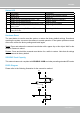
VIVOTEK NOTE: ► How does motion detection work? A C B D There are two motion detection parameters: Sensitivity and Percentage. In the illustration above, frame A and frame B are two sequential images. Pixel differences between the two frames are detected and highlighted in gray (frame C) and will be compared with the sensitivity setting. Sensitivity is a value that expresses the sensitivity to moving objects.
VIVOTEK Applications > DI and DO Advanced Mode Digital input: Select High or Low to define normal status for the digital input. The Network Camera will report the current status. Digital output: Select Grounded or Open to define normal status for the digital output. The Network Camera will show whether the trigger is activated or not. Set up the event source as DI on Event > Event settings > Trigger. Please refer to page 86 for detailed information.
VIVOTEK Applications > Audio detection Advanced Mode Audio detection, along with video motion detection, is applicable in the following scenarios: 1. Detection of activities not covered by camera view, e.g., a loud input by gun shots or breaking a door/ window. 2. A usually noisy environment, such as a factory, suddenly becomes quiet due to a breakdown of machines. 3. A PTZ camera can be directed to turn to a preset point by the occurrence of audio events. 4.
VIVOTEK IMPORTANT! • • • If the Alarm level and the received volume are set within a range of 20% on the wave diagram, frequent alarms will be triggered. It is recommended to set the Alarm level farther apart from the detected sound level. To configure and enable this feature, you must not configure video stream #1 into motion jpeg.
VIVOTEK Recording > Recording settings Advanced Mode This section explains how to configure the recording settings for the Network Camera. Recording Settings Insert your SD card and click here to test NOTE: ► Please remember to format your SD card when using for the first time. Please refer to page 109 for detailed information. Recording Settings Click Add to open the recording setting window.
VIVOTEK If you enable adaptive recording and enable time-shift cache stream on Camera A, only when an event is triggered on Camera A will the server record the full frame rate streaming data; otherwise, it will only request the I frame data during normal monitoring, thus effectively save lots of bandwidths and storage. NOTE: ► To enable adaptive recording, please make sure you’ve set up the trigger source such as Motion Detection, DI Device, Audio detection, or Manual Trigger.
VIVOTEK 2. Destination You can select the SD card or network storage (NAS) for the recorded video files. NAS server Click Add NAS server to open the server setting window and follow the steps below to set up: 1. Fill in the information for your server. For example: 3 Network storage path (\\server name or IP address\folder name) 1 User name and password for your server 2 4 2. Click Test to check the setting. The result will be shown in the pop-up window.
VIVOTEK If successful, you will receive a test.txt file on the network storage server. 3. Enter a server name. 4. Click Save to complete the settings and click Close to exit the page. ■ Capacity: You can select either the entire storage space available or specify a reserved space. The recording size limit must be larger than the reserved space for cyclic recording.
VIVOTEK The new recording name will appear on the recording page as shown below. To remove a recording setting from the list, select it and click Delete. ■ Video (Name): Click to open the Recording settings page to modify. ■ ON (Status): Click to manually adjust the Status. (ON: start recording; OFF: stop recording) ■ NAS or SD (Destination): Click to open the file list of recordings as shown below. For more information about folder naming rules, please refer to page 95 or page 110 for details.
VIVOTEK Local storage > SD card management This section explains how to manage the local storage on the Network Camera. Here you can view SD card status, and implement SD card control. SD card status This column shows the status and reserved space of your SD card. Please remember to format the SD card when using for the first time. no SD card SD card control ■ Enable cyclic storage: Check this item if you want to enable cyclic recording.
VIVOTEK Local storage > Content management This section explains how to manage the content of recorded videos on the Network Camera. Here you can search and view the records and view the searched results. Searching and Viewing the Records This column allows the user to set up search criteria for recorded data. If you do not select any criteria and click Search button, all recorded data will be listed in the Search Results column. ■ File attributes: Select one or more items as your search criteria.
VIVOTEK ■ View: Click on a search result which will highlight the selected item in purple as shown above. Click the View button and a media window will pop up to play back the selected file. For example: Click to adjust the image size ■ Download: Click on a search result to highlight the selected item in purple as shown above. Then click the Download button and a file download window will pop up for you to save the file.
VIVOTEK Appendix URL Commands for the Network Camera 1. Overview For some customers who already have their own web site or web control application, the Network Camera/Video Server can be easily integrated through URL syntax. This section specifies the external HTTP-based application programming interface. The HTTP-based camera interface provides the functionality to request a single image, control camera functions (PTZ, output relay etc.), and get and set internal parameter values.
VIVOTEK 3. General CGI URL Syntax and Parameters CGI parameters are written in lower-case and as one word without any underscores or other separators. When the CGI request includes internal camera parameters, these parameters must be written exactly as they are named in the camera or video server. The CGIs are organized in functionally-related directories under the cgi-bin directory. The file extension .cgi is required. Syntax: http:///cgi-bin/[/...]/.
VIVOTEK [&…] http:///cgi-bin/operator/getparam.cgi?[] [&…] http:///cgi-bin/admin/getparam.cgi?[] [&…] Where the should be [_] or [.]. If you do not specify any parameters, all the parameters on the server will be returned. If you specify only , the parameters of the related group will be returned. When querying parameter values, the current parameter values are returned.
VIVOTEK 6. Set Server Parameter Values Note: The access right depends on the URL directory. Method: GET/POST Syntax: http:///cgi-bin/anonymous/setparam.cgi? = [&=…][&update=][&return=] http:///cgi-bin/viewer/setparam.cgi? = [&=…][&update=] [&return=] http:///cgi-bin/operator/setparam.
VIVOTEK =\r\n [] Only the parameters that you set and are readable will be returned. Example: Set the IP address of server to 192.168.0.123: Request: http://myserver/cgi-bin/admin/setparam.cgi?network_ipaddress=192.168.0.123 Response: HTTP/1.0 200 OK\r\n Content-Type: text/html\r\n Context-Length: 33\r\n \r\n network.ipaddress=192.168.0.123\r\n 7.
VIVOTEK everything inside <> A description integer primary key SQLite data type. A 32-bit signed integer. The value is assigned a unique integer by the server. text SQLite data type. The value is a text string, stored using the database encoding (UTF-8, UTF-16BE or UTF-16-LE). coordinate x, y coordinate (eg. 0,0) window size window width and height (eg. 800x600) NOTE: The camera should not be restarted when parameters are changed. 7.
VIVOTEK ntp 6/6 NTP server. name>, *Do not use “skip to invoke , value. timezoneindex -489 ~ 529 320 6/6 Indicate timezone and area.
VIVOTEK Edinburgh, Lisbon, London 40: GMT 01:00 Amsterdam, Berlin, Rome, Stockholm, Vienna, Madrid, Paris 41: GMT 01:00 Warsaw, Budapest, Bern 80: GMT 02:00 Athens, Helsinki, Istanbul, Riga 81: GMT 02:00 Cairo 82: GMT 02:00 Lebanon, Minsk 83: GMT 02:00 Israel 120: GMT 03:00 Baghdad, Kuwait, Riyadh, Moscow, St.
VIVOTEK Darwin 400: GMT 10:00 Brisbane, Canberra, Melbourne, Sydney, Guam, Vladivostok 440: GMT 11:00 Magadan, Solomon Is., New Caledonia 480: GMT 12:00 Aucklan, Wellington, Fiji, Kamchatka, Marshall Is. 520: GMT 13:00 Nuku'Alofa daylight_enable 0 6/6 Enable automatic daylight saving time in time zone. daylight_dstactualmode 1 6/7 Check if current time is under daylight saving time.
VIVOTEK integer> restoreexceptnet Restore the system parameters to default values except (ipaddress, subnet, router, dns1, dns2, pppoe). This command can cooperate with other “restoreexceptXYZ” commands. When cooperating with others, the system parameters will be restored to the default value except for a union of the combined results. restoreexceptdst Restore the system parameters to default values except all daylight saving time settings.
VIVOTEK 7.1.1 system.info Subgroup of system: info (The fields in this group are unchangeable.) NAME VALUE DEFAULT SECURITY DESCRIPTION (get/set) modelname string[40] SD8362 0/7 Internal model name of the server (eg. IP7139) extendedmodelname string[40] SD8362 0/7 ODM specific model name of server (eg. DCS-5610). If it is not an ODM model, this field will be equal to “modelname” serialnumber mac 0/7 12 characters MAC address (without hyphens).
VIVOTEK 7.2 status Group: status NAME VALUE DEFAULT SECURITY DESCRIPTION (get/set) videoactualmodulation ntsc, pal 1 4/7 The actual modulation type (videoin.type=0). di_i<0~(ndi-1)> 0 1/7 0 => Inactive, normal 1 => Active, triggered (capability.ndi > 0) do_i<0~(ndo-1)> 0 1/7 0 => Inactive, normal 1 => Active, triggered (capability.
VIVOTEK 7.4 digital output behavior define Group: do_i<0~(ndo-1)> (capability.ndo > 0) NAME VALUE DEFAULT SECURITY DESCRIPTION (get/set) normalstate open, open 1/1 grounded Indicate open circuit or closed circuit (inactive status) 7.5 security Group: security NAME VALUE DEFAULT SECURITY DESCRIPTION (get/set) privilege_do view, operator, admin operator 6/6 Indicate which privileges and above can control digital output (capability.
VIVOTEK 7.6 network Group: network NAME VALUE DEFAULT SECURITY DESCRIPTION (get/set) preproces 7/6 An 32-bit integer, each bit can be set separately as follows: Bit 0 => HTTP service; Bit 1=> HTTPS service; Bit 2=> FTP service; Bit 3 => Two way audio and RTSP Streaming service; To stop service before changing its port settings. It’s recommended to set this parameter when change a service port to the port occupied by another service currently.
VIVOTEK address> router 6/6 Default gateway. 6/6 Primary DNS server. 6/6 Secondary DNS server. 6/6 Primary WINS server. 6/6 Secondary WINS server. address> dns1 dns2 wins1 wins2 7.6.1 802.1x Subgroup of network: ieee8021x (capability.protocol.ieee8021x > 0) NAME VALUE DEFAULT SECURITY DESCRIPTION (get/set) enable 0 6/6 Enable/disable IEEE 802.
VIVOTEK 7.6.2 QOS Subgroup of network: qos_cos (capability.protocol.qos.cos > 0) NAME VALUE DEFAULT SECURITY DESCRIPTION (get/set) enable 0 6/6 Enable/disable CoS (IEEE 802.1p) vlanid 1~4095 1 6/6 VLAN ID video 0~7 0 6/6 Video channel for CoS audio 0~7 0 6/6 Audio channel for CoS
VIVOTEK 7.6.4 FTP Subgroup of network: ftp NAME VALUE DEFAULT SECURITY DESCRIPTION (get/set) port 128 - User's Manual 21, 1025~65535 21 6/6 Local ftp server port.
VIVOTEK 7.6.5 HTTP Subgroup of network: http NAME VALUE DEFAULT SECURITY DESCRIPTION (get/set) port 80, 1025 ~ 80 1/6 HTTP port. 65535 alternateport 1025~65535 8080 6/6 Alternate HTTP port. authmode basic, basic 1/6 HTTP authentication mode. video.mjpg 1/6 HTTP server push access name for digest s0_accessname string[32] stream 1. (capability.protocol.spush_mjpeg =1 and capability.nmediastream > 0) s1_accessname string[32] video2.
VIVOTEK 1) anonymousviewing 0 1/6 Enable anoymous streaming viewing. 7.6.6 HTTPS port Subgroup of network: https_port (capability.protocol.https > 0) NAME VALUE DEFAULT SECURITY DESCRIPTION (get/set) port 443, 1025 ~ 443 1/6 HTTPS port. 65535 7.6.7 RTSP Subgroup of network: rtsp (capability.protocol.rtsp > 0) NAME VALUE DEFAULT SECURITY DESCRIPTION (get/set) port 554, 1025 ~ 554 1/6 65535 anonymousviewing RTSP port. (capability.protocol.
VIVOTEK stream4 (capability.protocol.rtsp=1 and capability.nmediastream > 3) S4_accessname liveany.sdp 1/6 RTSP access name for stream5 (capability.protocol.rtsp=1 and capability.nmediastream > 4) For some models, it is used for anystream. (capability.protocol.rtsp=1 and capability.nanystream = 1) s0_audiotrack 0 1/6 Enable audio for stream1. s1_audiotrack 0 1/6 Enable audio for stream2. s2_audiotrack 0 1/6 Enable audio for stream3.
VIVOTEK 7.6.8 SIP port Subgroup of network: sip (capability.protocol.sip> 0) NAME VALUE DEFAULT SECURITY DESCRIPTION (get/set) port 1025 ~ 65535 5060 1/6 SIP port. 7.6.9 RTP port Subgroup of network: rtp NAME VALUE DEFAULT SECURITY DESCRIPTION (get/set) videoport 1025 ~ 65535 5556 6/6 Video channel port for RTP. (capability.protocol.rtp_unicast=1) audioport 1025 ~ 65535 5558 6/6 Audio channel port for RTP. (capability.protocol.rtp_unicast=1) 7.6.
VIVOTEK 0 => allow 1 => deny ipv4list_i<0~9> Single address: 6/6 IPv4 address list. 6/6 IPv6 address list. Network address: Range address: ipv6list_i<0~9> String[44] 7.8 Video input Group: videoin NAME VALUE DEFAULT SECURITY DESCRIPTION (get/set) cmosfreq 50, 60 60 4/4 CMOS frequency. (capability.videoin.
VIVOTEK 1(support) Bit 5 => Support focus operation; 0(not support), 1(support) text string[16] 1/4 Enclose caption. imprinttimestamp 0 4/4 Overlay time stamp on video. options quality, quality 4/4 Video input option: framerate (1) Full HD (MAX1080P 30fps) (2) Exceptional frame rate ( 720P 60fps) 7.8.
VIVOTEK Bit 2 => Support pan operation; 0(not support), 1(support) Bit 3 => Support tilt operation; 0(not support), 1(support) Bit 4 => Support zoom operation; 0(not support), 1(support) Bit 5 => Support focus operation; 0(not support), 1(support) text string[16] 1/4 Enclose caption. imprinttimestamp 0 4/4 Overlay time stamp on video.
VIVOTEK 1 = worst quality, 5 = best quality. 100 is percentage mode. s<0~(m-1)>_mpeg4_qvalue 2~31 7 4/4 Manual video quality level input. (s<0~(m-1)>_mpeg4_qua nt = 99) s<0~(m-1)>_mpeg4_qperce 1~100 29 4/4 nt Manual video quality level input. (s<0~(m-1)>_mpeg4_qua nt = 100) s<0~(m-1)>_mpeg4_bitrate 1000~160000 51200 4/4 Set bit rate in bps when 00 choosing cbr in
VIVOTEK s<0~(m-1)>_h264_bitrate 1000~160000 30000000 4/4 00 Set bit rate in bps when choosing cbr in “ratecontrolmode”. s<0~(m-1)>_h264_maxfra 1~25, me 26~30 (only 30 1/4 Set maximum frame rate in fps (for h264). for NTSC or 60Hz CMOS) s<0~(m-1)>_h264_profile 0~2 1 1/4 Indicate H264 profiles 0: baseline 1: main profile 2: high profile s<0~(m-1)>_mjpeg_quant 1~5 3 4/4 99, 100 Quality of JPEG video. 99 is the customized manual input setting.
VIVOTEK agc 1~12 5 4/4 (6db~28db) enableblc 0~1 Set auto gain control to normal level or MAX level. 0 4/4 Enable backlight compensation (exposurecontrol => auto with IRCut) shutterpriority 0~14 5 4/4 Exposure time (exposurecontrol( => shutter priority) irispriority 1~13 13 4/4 (F1.6 ~ F14) Iris adjustment (exposurecontrol => Iris priority) irismanual 1~13 13 4/4 (F1.
VIVOTEK (wdr_mode : 1) wdr_sensitivity 0~2 1 4/4 WDR strength 0: low 1: medium 2: high (wdr_mode: 2) 7.8.1.1 Alternative video input profiles per channel In addition to the primary setting of video input, there can be alternative profile video input setting for each channel which might be for different scene of light (daytime or nighttime). Group: videoin_c0_profile_i<0~(m-1)> (capability.
VIVOTEK shutterspeed 0~14 5 4/4 (1/1 ~ 1/10000) gain 0~15 (exposurecontrol => manual) 5 4/4 (0db ~ 28db) exposurecontrol 0~3 Exposure time Gain control (exposurecontrol => manual) 0 4/4 Select exposure mode. 0 => Auto with IRCut 1 => Shutter priority 2 => Iris priority 3 => Manual mode exposurelevel 0~12 6 4/4 Exposure level whitebalance auto, manual manual 4/4 “auto” indicates auto white balance. “manual” indicates keep current value.
VIVOTEK 1: medium 2: high (wdr_mode: 2) 7.10 IR cut control Group: ircutcontrol (capability.nvideoinprofile > 0) NAME VALUE DEFAULT SECURITY DESCRIPTION (get/set) daymodebegintime 00:00~23:59 07:00 6/6 Day mode begin time daymodeendtime 00:00~23:59 18:00 6/6 Day mod end time sensitivity 0~28 14 6/6 Sensitivity of IR cut filter 7.
VIVOTEK according to mode settings. 7.12 Image setting for preview Group: imagepreview_c<0~(n-1)> for n channel products NAME VALUE DEFAULT SECURITY DESCRIPTION (get/set) brightness -5~5 -5 4/4 Adjust brightness of image according to mode settings. saturation -5~5 0 4/4 Adjust saturation of image according to mode settings. 100 for saturation percentage mode. contrast -5 ~ 5 0 4/4 Adjust contrast of image according to mode settings.
VIVOTEK Group: audioin_c<0~(n-1)> for n channel products (capability.audioin>0) NAME VALUE DEFAULT SECURITY DESCRIPTION (get/set) mute 0, 1 0 4/4 Enable audio mute. gain 1~100 69 4/4 Gain of input. (audioin_c<0~(n-1)>_source = linein) s<0~(m-1)>_codectype aac4, aac4 4/4 Set audio codec type for input. 16000 4/4 Set AAC4 bitrate in bps. 12200 4/4 Set AMR bitrate in bps. pcmu 4/4 Set G.711 mode.
VIVOTEK 7.16 Motion detection settings Group: motion_c<0~(n-1)> for n channel product NAME VALUE DEFAULT SECURITY DESCRIPTION (get/set) enable 0 4/4 Enable motion detection. win_i<0~2>_enable 0 4/4 Enable motion window 1~3. win_i<0~2>_name string[14] 4/4 Name of motion window 1~3. win_i<0~2>_left 0 ~ 320 0 4/4 Left coordinate of window position. win_i<0~2>_top 0 ~ 240 0 4/4 Top coordinate of window position.
VIVOTEK of window position. i<0~(m-1)>_win_i<0~2>_top 0 ~ 240 0 4/4 Top coordinate of window position. i<0~(m-1)>_win_i<0~2>_width 0 ~ 320 0 4/4 Width of motion detection window. i<0~(m-1)>_win_i<0~2>_height 0 ~ 240 0 4/4 Height of motion detection window. i<0~(m-1)>_win_i<0~2>_objsize 0 ~ 100 0 4/4 Percent of motion detection window. i<0~(m-1)>_win_i<0~2>_sensitivity 0 ~ 100 0 4/4 Sensitivity of motion detection window. 7.
VIVOTEK DyndnsCustom, (dynamic) TZO, DyndnsCustom => dyndns.org DHS, (custom) DynInterfree, TZO => tzo.com CustomSafe100, DHS => dhs.org PeanutHull, DynInterfree =>dyn-interfree.it IODATA, CustomSafe100 => DO_JP, Custom server using safe100 MYDNS_JP, method customizeddyndns, PeanutHull => PeanutHull DP21, IODATA => iodata.jp NetHome, DO JP => ddo.jp ADAMA_LAND, MYDNS JP => mydns.
VIVOTEK CustomizedTZO => Customized server using TZO method _ho string[128] 6/6 Your DDNS hostname. string[64] 6/6 Your user name or email to login to stname _us ernameemail the DDNS service provider _pa string[64] 6/6 Your password or key to login to the sswordkey DDNS service provider. _se string[128] 6/6 The server name for safe100.
VIVOTEK forwarding service. upnpnatstatus 0~3 0 6/7 The status of UPnP port forwarding, used internally. 0 = OK, 1 = FAIL, 2 = no IGD router, 3 = no need for port forwarding 7.22 System log Group: syslog NAME VALUE DEFAULT SECURITY DESCRIPTION (get/set) enableremotelog 0 6/6 Enable remote log. serverip 6/6 Log server IP address. serverport 514, 514 6/6 Server port used for log.
VIVOTEK 7.23 camera PTZ control Group: camctrl_c<0~(n-1)> for n channel product (capability.ptzenabled) NAME VALUE DEFAULT SECURITY DESCRIPTION (get/set) panspeed -5 ~ 5 0 1/4 Pan speed tiltspeed -5 ~ 5 0 1/4 Tilt speed zoomspeed -5 ~ 5 0 1/4 Zoom speed autospeed -5 ~ 5 0 1/4 Auto pan speed focusspeed -5 ~ 5 0 1/4 Auto focus speed preset_i<0~(npreset- string[40] 1/4 Name of the preset location.
VIVOTEK 7.25 SNMP Group: snmp (capability.snmp > 0) NAME VALUE DEFAULT SECURITY DESCRIPTION (get/set) v2 0~1 0 6/6 SNMP v2 enabled. 0 for disable, 1 for enable v3 0~1 0 6/6 SNMP v3 enabled.
VIVOTEK logo_powerbyvvtk_hidden 0 1/6 0 => display the power by vivotek logo 1 => hide the power by vivotek logo custombutton_manualtrigger_s 1 1/6 Show or hide manual trigger how (VI) button in homepage 0 -> Hidden 1 -> Visible theme_option 1~4 1 1/6 1~3: One of the default themes. 4: Custom definition. theme_color_font string[7] #ffffff 1/6 Font color theme_color_configfont string[7] #ffffff 1/6 Font color of configuration area.
VIVOTEK bootuptime nir 0, built-in IR and extir for external IR) npir 0, 0 0/7 Number of PIRs. 1 0/7 Number of digital inputs. 3 0/7 Number of virtual inputs ndi 0, nvi 0, ndo 0, 1 0/7 Number of digital outputs. 1 0/7 Number of audio inputs. 1 0/7 Number of audio outputs.
VIVOTEK ptzenabled 0, 189 0/7 An 32-bit integer, each bit can be set separately as follows: Bit 0 => Support camera control function; 0(not support), 1(support) Bit 1 => Built-in or external camera; 0(external), 1(built-in) Bit 2 => Support pan operation, 0(not support), 1(support) Bit 3 => Support tilt operation; 0(not support), 1(support) Bit 4 => Support zoom operation; 0(not support), 1(support) Bit 5 => Support focus operation; 0(not support), 1(support) Bit 6 => Support iris ope
VIVOTEK 1(fields are invalid) evctrlchannel 1 0/7 Indicate whether to support HTTP tunnel for event/control transfer. joystick 1 0/7 Indicate whether to support joystick control. storage_dbenabled 1 0/7 Media files are indexed in database. ptzenabledclient 0 0/7 Indicate whether to support ptz client protocol_https < boolean > 1 0/7 Indicate whether to support HTTP over SSL. protocol_rtsp < boolean > 1 0/7 Indicate whether to support RTSP.
VIVOTEK videoin_type 0, 1, 2 2 0/7 0 => Interlaced CCD 1 => Progressive CCD 2 => CMOS videoin_resolution 1280x1024 0/7 Available resolutions list. 0/7 Available maximum frame videoin_maxframerate 30, videoin_codec mpeg4.
VIVOTEK audio_lineout 1 0/7 Indicate whether to support line output. audio_headphoneout 0 0/7 Indicate whether to support headphone output. audioin_codec aac4, gamr, g711 aac4, gamr, audioout_codec g711 g711 0/7 Available codec list for SIP. 0 0/7 Indicate whether to camctrl_httptunnel support httptunnel.
VIVOTEK 802.11b+. wireless_s802dot11g 0 0/7 Indicate whether to support wireless 802.11g. wireless_encrypt_wep 0 0/7 Indicate whether to support wireless WEP. wireless_encrypt_wpa 0 0/7 Indicate whether to support wireless WPA. wireless_encrypt_wpa2 0 0/7 Indicate whether to support wireless WPA2.
VIVOTEK detection. test_ac 1 0/7 Indicate whether to support test ac key. version_onvifdaemon 1.5.0.0 0/7 Indicate ONVIF daemon version image_wdrc 0 0/7 Indicate whether to support WDR enhanced. image_ iristype piris, dciris 0/7 Indicate iris type. image_ focusassist 0 0/7 Indicate whether to support focus assist. 7.
VIVOTEK trigger boot, boot 6/6 Indicate the trigger condition: di, “boot” = System boot motion, “di”= Digital input seq, “motion” = Video motion detection recnotify, “seq” = Periodic condition volalarm “recnotify” = Recording notification. “volalarm” = Audio detection. triggerstatus String[40] trigger 6/6 The status for event trigger di 1 6/6 Indicate the source id of di trigger. This field is required when trigger condition is “di”. One bit represents one digital input.
VIVOTEK begintime hh:mm 00:00 6/6 Begin time of the weekly schedule. endtime hh:mm 24:00 6/6 End time of the weekly schedule. (00:00 ~ 24:00 sets schedule as always on) action_do_i<0~(ndo-1) 0, 1 0 6/6 >_enable action_do_i<0~(ndo-1) output. 1~999 1 6/6 >_duration action_goto_enable 0 6/6 Enable/disable ptz goto preset position on event triggered. string[40] 6/6 action_cf_enable Duration of the digital output trigger in seconds.
VIVOTEK action_ patrol _server 0~255 0 6/6 Indicate the target servers to which (only for VS series) the snapshots taken during patrol dwelling time should be sent. One bit represents one application server (server_i0~i4). bit0 (LSB) = server_i0. bit1 = server_i1. bit2 = server_i2. bit3 = server_i3. bit4 = server_i4. For example, enable server_i0, server_i2, and server_i4 as notification servers; the notifyserver value is 21. 7.
VIVOTEK email_address string[128] NULL 6/6 Email server address. email_sslmode 0, 1 0 6/6 Enable support SSL. email_port 0~65535 25 6/6 Port to connect to the server. email_username string[64] NULL 6/6 Username to log in to the server. email_passwd string[64] NULL 6/6 Password of the user. email_senderemail string[128] NULL 6/6 Email address of the sender. email_recipientemail string[128] NULL 6/6 Email address of the recipient.
VIVOTEK snapshot_datesuffix 0, 1 0 6/6 Add date and time suffix to filename: 1 = Add date and time suffix. 0 = Do not add. snapshot_preevent 0~7 1 6/6 Indicates the number of pre-event images. snapshot_postevent 0~7 1 6/6 The number of post-event images. videoclip_source 0 6/6 Indicate the source of media stream. 0 means the first stream. 1 means the second stream and etc. 2 means the third stream and etc. 3 means the fourth stream and etc.
VIVOTEK source 0~3 0 6/6 Indicate the source of media stream. 0 means the first stream. 1 means the second stream and so on. limitsize 0,1 0 6/6 0: Entire free space mechanism 1: Limit recording size mechanism cyclic 0,1 0 6/6 0: Disable cyclic recording 1: Enable cyclic recording notify 0,1 1 6/6 0: Disable recording notification 1: Enable recording notification notifyserver 0~31 0 6/6 Indicate which notification server is scheduled.
VIVOTEK endtime hh:mm 24:00 6/6 End time of the weekly schedule. (00:00~24:00 indicates schedule always on) prefix string[16] 6/6 Indicate the prefix of the filename. cyclesize 200~ 100 6/6 The maximum size for cycle recording in Kbytes when choosing to limit recording size. reserveamount 0~ 100 6/6 The reserved amount in Mbytes when choosing cyclic recording mechanism. dest cf, cf 6/6 0~4 The destination to store the recorded data. “cf” means local storage (CF or SD card).
VIVOTEK certificate manually. install => Create certificate request and install. status -3 ~ 1 0 6/7 Specify the https status. -3 = Certificate not installed -2 = Invalid public key -1 = Waiting for certificate 0 = Not installed 1 = Active countryname string[2] TW 6/6 Country name in the certificate information. stateorprovincename string[128] Asia 6/6 State or province name in the certificate information. localityname string[128] Asia 6/6 The locality name in the certificate information.
VIVOTEK 8. Useful Functions 8.1 Drive the Digital Output (capability.ndo > 0) Note: This request requires Viewer privileges. Method: GET/POST Syntax: http:///cgi-bin/dido/setdo.cgi?do1=[&do2=] [&do3=][&do4=] Where state is 0 or 1; “0” means inactive or normal state, while “1” means active or triggered state.
VIVOTEK Example: Query the status of digital input 1 . Request: http://myserver/cgi-bin/dido/getdi.cgi?di1 Response: HTTP/1.0 200 OK\r\n Content-Type: text/plain\r\n Content-Length: 7\r\n \r\n di1=1\r\n 8.3 Query Status of the Digital Output (capability.ndo > 0) Note: This request requires Viewer privileges Method: GET/POST Syntax: http:///cgi-bin/dido/getdo.cgi?[do0][&do1][&do2][&do3] If no parameter is specified, all the digital output statuses will be returned. Return: HTTP/1.
VIVOTEK \r\n do1=1\r\n 8.4 3D Privacy Mask Note: This request requires admin user privilege You can set privacy mask only at zoom 1x. To go back to zoom 1x directly, please send this cgi command: "/cgi-bin/camctrl/camposition.cgi?setzoom=0" Method: GET/POST Syntax: http:///cgi-bin/admin/setpm3d.
VIVOTEK resolution> quality 1~5 3 The quality of the image. streamid 0~(m-1) The server will return the most up-to-date snapshot of the selected channel and stream in JPEG format. The size and quality of the image will be set according to the video settings on the server. Return: HTTP/1.0 200 OK\r\n Content-Type: image/jpeg\r\n [Content-Length: \r\n] 8.
VIVOTEK Return operator Operator privilege. admin Administrator privilege. Redirect to the page after the parameter is assigned. The can be a full URL path or relative path according to the current path. If you omit this parameter, it will redirect to an empty page. 8.7 System Logs Note: This request require Administrator privileges. Method: GET/POST Syntax: http:///cgi-bin/admin/syslog.cgi Server will return the most up-to-date system log.
VIVOTEK 8.9 Camera Control (capability.ptzenabled) Note: This request requires Viewer privileges. Method: GET/POST Syntax: http:///cgi-bin/viewer/camctrl.
VIVOTEK speedfocus -5 ~ 5 Set the focus speed. speedapp -5 ~ 5 Set the auto pan/patrol speed. auto pan Auto pan. patrol Auto patrol. stop Stop camera. wide Zoom larger view with current speed. tele Zoom further with current speed. stop Stop zoom. wide or tele Zoom without stopping for larger view or further view with zs zoom zooming speed, used for joystick control. zs 0~6 Set the speed of zooming, “0” means stop.
VIVOTEK 8.10 ePTZ Camera Control (capability.eptz > 0) Note: This request requires camctrl privileges. Method: GET/POST Syntax: http:///cgi-bin/camctrl/eCamCtrl.
VIVOTEK zooming tele Zoom further with current speed. wide or tele Zoom without stopping for larger view or further view with zs speed, used for joystick control. zs 0~6 Set the speed of zooming, “0” means stop. vx The direction of movement, used for joystick control. vy vs 0~7 Set the speed of movement, “0” means stop. x x-coordinate clicked by user. It will be the x-coordinate of center after movement. y y-coordinate clicked by user.
VIVOTEK PARAMETER VALUE DESCRIPTION recall Text string less than 30 One of the present positions to recall. characters channel <0~(n-1)> Channel of the video source. return Redirect to the page after the parameter is assigned. The can be a full URL path or relative path according to the current path. If you omit this parameter, it will redirect to an empty page. 8.12 ePTZ Recall (capability.eptz > 0) Note: This request requires camctrl privileges.
VIVOTEK PARAMETER VALUE DESCRIPTION addpos channel <0~(n-1)> Channel of the video source. delpos return Redirect to the page after the parameter is assigned. The can be a full URL path or relative path according to the current path. If you omit this parameter, it will redirect to an empty page.
VIVOTEK 8.15 IP Filtering Note: This request requires Administrator access privileges. Method: GET/POST Syntax: http:///cgi-bin/admin/ipfilter.cgi?type[=] http:///cgi-bin/admin/ipfilter.cgi?method=add&ip=[&index=] [&return=] http:///cgi-bin/admin/ipfilter.
VIVOTEK pragma: no-cache cache-control: no-cache ------------------------------------------------------------------------POST /cgi-bin/operator/uartchannel.cgi x-sessioncookie: string[22] content-type: application/x-vvtk-tunnelled pragma : no-cache cache-control : no-cache content-length: 32767 expires: Sun, 9 Jam 1972 00:00:00 GMT User must use GET and POST to establish two channels for downstream and upstream.
VIVOTEK x-sessioncookie: string[22] content-type: application/x-vvtk-tunnelled pragma : no-cache cache-control : no-cache content-length: 32767 expires: Sun, 9 Jam 1972 00:00:00 GMT User must use GET and POST to establish two channels for downstream and upstream. The x-sessioncookie in GET and POST should be the same to be recognized as a pair for one session. The contents of upstream should be base64 encoded to be able to pass through the proxy server.
VIVOTEK “m” is the stream number. For details on streaming protocol, please refer to the “control signaling” and “data format” documents. 8.20 Senddata (capability.nuart > 0) Note: This request requires Viewer privileges. Method: GET/POST Syntax: http:///cgi-bin/viewer/senddata.cgi? [com=][&data=][&flush=] [&wait=] [&read=] PARAMETER VALUE DESCRIPTION com 1 ~
VIVOTEK 8.21 Storage managements (capability.storage.dbenabled > 0) Note: This request requires administrator privileges. Method: GET and POST Syntax: http:///cgi-bin/admin/lsctrl.cgi?cmd=[&=…] The commands usage and their input arguments are as follows. PARAMETER VALUE DESCRIPTION cmd_type Required. Command to be executed, including search, insert, delete, update, and queryStatus.
VIVOTEK Indicate if the file is locked or not. 0: file is not locked. 1: file is locked. A locked file would not be removed from UI or cyclic storage. triggerTime Optional. Indicate the event trigger time. (not the file created time) Format is “YYYY-MM-DD HH:MM:SS” Please embrace your input value with single quotes. Ex. triggerTime=’2008-01-01 00:00:00’ If you want to search for a time period, please apply “TO” operation. Ex.
VIVOTEK label Required. Identify the designated record. Ex. label=1 isLocked Required. Indicate if the file is locked or not. Ex. Update records whose key numbers are 1 and 5 to be locked status. http:///cgi-bin/admin/lsctrl.cgi?cmd=update&isLocked=1&label=1&label=5 Ex. Update records whose key numbers are 2 and 3 to be unlocked status. http:///cgi-bin/admin/lsctrl.
VIVOTEK return state after duration. it cannot accept new requests. Redirect to the page after the request is completely assigned. The can be a full URL path or relative path according the current path. If you omit this parameter, it will redirect to an empty page. Return Code Description 200 The request is successfully executed. 400 The request cannot be assigned, ex. incorrect parameters. Examples: setvi.
VIVOTEK “m” is the timeshift stream index. For details on timeshift stream, please refer to the “TimeshiftCaching” documents. PARAMETER VALUE DEFAULT DESCRIPTION maxsft tsmode normal, adaptive normal => Full FPS all the time. adaptive => Default send only I-frame for MP4 and H.264, and send 1 FPS for MJPEG.
VIVOTEK 8. 24 Open Anystream (capability.nanystream > 0) Note: This request requires Viewer access privileges. Syntax: For HTTP push server (MJPEG): http:///videoany.mjpg?codectype=mjpeg[&resolution=&mjpeg_quant=& mjpeg_qvalue=&mjpeg_maxframe=] For RTSP (MPEG4), the user needs to input the URL below into an RTSP compatible player. rtsp:///liveany.
VIVOTEK mpeg4_ratecontrolmode cbr, vbr vbr cbr: constant bitrate vbr: fix quality mpeg4_quant 0, 1~5 3 Quality of video when choosing vbr in 99, 1~5 “mpeg4_ratecontrolmode”. 0,99 is the customized manual input setting. 1 = worst quality, 5 = best quality. mpeg4_qvalue 1~31 7 Manual video quality level input.
VIVOTEK dependent> User's Manual - 189
VIVOTEK Technical Specifications Technical Specifications Pan/Tilt/Zoom Alarm and Event Management .Pan range: 360° continuous rotation .Tilt range: 0° ~ 90° flip .20x optical zoom .Pan speed: 0.1° ~ 300°/sec .Tilt speed: 0.
VIVOTEK Technology License Notice MPEG-4 AAC Technology THIS PRODUCT IS LICENSED UNDER THE MPEG-4 AAC AUDIO PATENT LICENSE. THIS PRODUCT MAY NOT BE DECOMPILED, REVERSE-ENGINEERED OR COPIED, EXCEPT WITH REGARD TO PC SOFTWARE, OF WHICH YOU MAY MAKE SINGLE COPIES FOR ARCHIVAL PURPOSES. FOR MORE INFORMATION, PLEASE REFER TO HTTP://WWW.VIALICENSING.COM.
VIVOTEK Electromagnetic Compatibility (EMC) FCC Statement This device compiles with FCC Rules Part 15. Operation is subject to the following two conditions. ■ This device may not cause harmful interference, and ■ This device must accept any interference received, including interference that may cause undesired operation. This equipment has been tested and found to comply with the limits for a Class A digital device, pursuant to Part 15 of the FCC Rules.