IP8352 Supreme Night Visibility • 1.
VIVOTEK Table of Contents Overview 4 Read Before Use �������������������������������������������������������������������������������������������������������������������������������������5 Package Contents �����������������������������������������������������������������������������������������������������������������������������������5 Symbols and Statements
VIVOTEK Day/Night Settings ����������������������������������������������������������������������������������������������������������������������������������������������� 70 Preference ���������������������������������������������������������������������������������������������������������������������������������������������������������� 71 Exposure ����������������������������������������������������������������������������������������������������������������������������������������������������������� 73
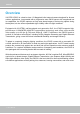
VIVOTEK Overview VIVOTEK IP8352 is a best-in-class 1�3-Megapixel bullet network camera designed for diverse outdoor applications� Incorporated with a progressive scan CMOS sensor with exceptional low lux capabilities, the IP8352 captures not only razor-sharp images of fast-moving objects during the daytime, but also offers unparalleled night visibility under low light conditions� Equipped with VIVOTEK’s self-developed next-generation SoC, the IP8352 supports highperformance H�264/MPEG-4/MJPEG compression t
VIVOTEK Read Before Use The use of surveillance devices may be prohibited by law in your country� The Network Camera is not only a high-performance web-ready camera but can also be part of a flexible surveillance system.
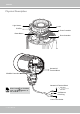
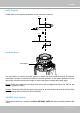
VIVOTEK Physical Description Light Sensor Lens IR LEDs Focus Controller Reset Button Zoom Controller General I/O Terminal Block SD/SDHC Card Slot General I/O Terminal Block When inserting an SD/SDHC card, note the orientation of the contacts� + AC 24V + - AC 24V - Gb Ethernet RJ45 Plug Power Cord Socket 6 - User's Manual
VIVOTEK Hardware Installation 1� Attach the alignment sticker to the wall� Drill three holes into the wall� Then hammer the supplied plastic anchors into the holes and secure the plate with supplied screws� 2� Feed the cables through the front opening of the wall mount bracket� (If you want to use external devices such as sensors and alarms, please refer to the assembling steps on the next page�) 3� Hang the wall mount bracket on the plate� 4� Fix the Network Camera on the wall mount bracket with two screw
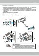
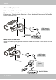
VIVOTEK Waterproof Connector Components of the Waterproof Connector IO Block Pin Definitions Rubber (A) Screw Nut (B) 1 2 3 4 5 6 7 8 9 10 Seal (C) Seals (D) Housing (E) Sealing Nut (F) 1 2 3 4 5 6 7 8 9 10 Power +12V Digital Output Digital Input Ground RS485 + RS485 Ground Audio Input Ground Audio Output Assembling Steps 1� Disassemble the components of the waterproof connector into part (A) ~ (F) as shown above� 2� Remove the rubber stopper from the bottom of the Network Camera and secure the rubb
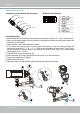
VIVOTEK DI/DO Diagram Please refer to the following illustration for the connection method� 12V PIN 1 Power+12V PIN 2 Digital output +12V PIN 3 Digital input PIN 4 Ground Hardware Reset Reset Button The reset button is used to reset the system or restore the factory default settings� Sometimes resetting the system can return the camera to normal operation� If the system problems remain after reset, press the reset button longer to restore the factory settings and install again� Reset: Press and relea
VIVOTEK Network Deployment When using a PoE-enabled switch The Network Camera is PoE-compliant, allowing transmission of power and data via a single Ethernet cable� Follow the below illustration to connect the Network Camera to a PoE-enabled switch via Ethernet cable� RJ45 Female/ Female Coupler PoE Switch POWER COLLISION 1 2 3 4 5 LINK RECEIVE PARTITION When using a non-PoE switch Use a PoE power injector (optional) to connect between the Network Camera and a non-PoE switch� RJ45 Female/ Female
VIVOTEK Network Deployment Setting up the Network Camera over the Internet There are several ways to set up the Network Camera over the Internet� The first way is to set up the Network Camera behind a router� The second way is to utilize a static IP� The third way is to use PPPoE� Internet connection via a router Before enabling the access to the Network Camera over the Internet, make sure you have a router and follow the steps below� 1� Connect your Network Camera behind a router, the Internet environment
VIVOTEK Internet connection with static IP Choose this connection type if you are required to use a static IP for the Network Camera� Please refer to LAN configuration on page 51 for details.
VIVOTEK Software Installation Installation Wizard 2 (IW2), free-bundled software included on the product CD, helps you set up your Network Camera on the LAN� 1� Install IW2 under the Software Utility directory from the software CD� Double click the IW2 shortcut on your desktop to launch the program� IW2 Installation Wizard 2 2� The program will conduct an analysis of your network environment� After your network environment is analyzed, please click Next to continue the program� 3� The program will sear
VIVOTEK Ready to Use 1� A browser session with the Network Camera should prompt as shown below� 2� You should be able to see live video from your camera� You may also install the 32-channel recording software from the software CD in a deployment consisting of multiple cameras� For its installation details, please refer to its related documents� 3� Unscrew the zoom controller to adjust the zoom factor� Upon completion, tighten the zoom controller� 4� Unscrew the focus controller to adjust the focus range�
VIVOTEK 5� Tighten the lens cover� 6� Replace the moisture absorber with a new one if you open the back cover during the installation procedure� 6 IMPORTANT! 5 Please tear down the aluminum foil vacuum bag and take out the moisture absorber, and then replace it with the absorber in kit using a double-sided tape� NOTE: If you want to use the supplied sun shield for outdoor environments, please follow the steps below to install: 1� Tighten the supplied two screws� 2� Attach the supplied sun shield to the
VIVOTEK Accessing the Network Camera This chapter explains how to access the Network Camera through web browsers, RTSP players, 3GPP-compatible mobile devices, and VIVOTEK recording software� Using Web Browsers Use Installation Wizard 2 (IW2) to access the Network Cameras on the LAN� If your network environment is not a LAN, follow these steps to access the Netwotk Camera: 1� Launch your web browser (ex� Microsoft® Internet Explorer or Mozilla Firefox)� 2.
VIVOTEK NOTE: 1� By default, your Network Camera is not password-protected� To prevent unauthorized access, it is highly recommended to configure a password for your camera later.
VIVOTEK Using RTSP Players To view the H�264/MPEG-4 streaming media using RTSP players, you can use one of the following players that support RTSP streaming� Quick Time Player Real Player 1� Launch the RTSP player� 2� Choose File > Open URL� A URL dialog box will prompt� 3� The address format is rtsp://:/ As most ISPs and players only allow RTSP streaming through port number 554, please set the RTSP port to 554� For more information,
VIVOTEK Using 3GPP-compatible Mobile Devices To view the streaming media through 3GPP-compatible mobile devices, make sure the Network Camera can be accessed over the Internet� For more information on how to set up the Network Camera over the Internet, please refer to Setup the Network Camera over the Internet on page 11� To utilize this feature, please check the following settings on your Network Camera: 1� Because most players on 3GPP mobile phones do not support RTSP authentication, make sure the authen
VIVOTEK Using VIVOTEK Recording Software The product software CD also contains recording software, allowing simultaneous monitoring and video recording for multiple Network Cameras� Please install the recording software; then launch the program to add the Network Camera to the Channel list� For detailed information about how to use the recording software, please refer to the user’s manual of the software or download it from http://www�vivotek�com� 20 - User's Manual
VIVOTEK Main Page This chapter explains the screen elements on the main page� It is composed of the following sections: VIVOTEK INC. Logo, Host Name, Camera Control Area, Configuration Area, and Live Video Window� VIVOTEK INC. Logo Resize Buttons Host Name Camera Control Area Hide Button Live View Window Configuration Area VIVOTEK INC. Logo Click this logo to visit the VIVOTEK website� Host Name The host name can be customized to fit your needs.
VIVOTEK Focus Assist Button: Follow the steps below to manually fine-tune the camera’s focus. 1. Manually adjust the zoom controller of the camera lens to fix the camer’s view angle. 2� Click on the “On” button of the Focus Assist function on the homepage session with the camera to start the focus assist function� The Live View window will automatically enter the full screen mode� Stream is being adjusted Focus N 4 Zoom T 3 ∞ W 3.
VIVOTEK Global View: Click on this item to display the Global The viewing region View window� The Global View window contains a full of the current video stream view image (the largest frame size of the captured video) and a floating frame (the viewing region of the current video stream).
VIVOTEK H�264 / MPEG-4 Protocol and Media Options: The transmission protocol and media options for H�264 / MPEG-4 video streaming. For further configuration, please refer to Client Settings on page 26. Time: Display the current time. For further configuration, please refer to Media > Image > Genral settings on page 69� Title and Time: The video title and time can be stamped on the streaming video.
VIVOTEK ■ The following window is displayed when the video mode is set to MJPEG: Video Title Title and Time Video (HTTP-V) 2011/03/10 17:08:56 Time Video 17:08:56 2011/03/10 Video Control Buttons Video Title: The video title can be configured.
VIVOTEK Client Settings This chapter explains how to select the stream transmission mode and saving options on the local computer� When completed with the settings on this page, click Save on the page bottom to enable the settings� H.264 / MPEG-4 Media Options H.264/MPEG-4 Media Options Select to stream video or audio data or both� This is enabled only when the video mode is set to H�264 or MPEG-4� H.264 / MPEG-4 Protocol Options H.
VIVOTEK MP4 Saving Options Users can record live video as they are watching it by clicking page. Here, you can specify the storage destination and file name. Start MP4 Recording on the main Folder: Specify a storage destination for the recorded video files. File name prefix: Enter the text that will be appended to the front of the video file name. Add date and time suffix to the file name: Select this option to append the date and time to the end of the file name.
VIVOTEK Configuration Click Configuration on the main page to enter the camera setting pages� Note that only Administrators can access the configuration page.
VIVOTEK Advanced Mode Navigation Area Configuration List Click to switch to Basic Mode Firmware Version Each function on the configuration list will be explained in the following sections. Those functions that are displayed only in Advanced Mode are marked with Advanced Mode � If you want to set up advanced functions, please click on [Advanced Mode] at the bottom of the configuration list.
VIVOTEK System time Keep current date and time: Select this option to preserve the current date and time of the Network Camera� The Network Camera’s internal real-time clock maintains the date and time even when the power of the system is turned off� Sync with computer time: Select this option to synchronize the date and time of the Network Camera with the local computer� The read-only date and time of the PC is displayed as updated� Manual: The administrator can enter the date and time manually� Note tha
VIVOTEK System > Homepage layout Advanced Mode This section explains how to set up your own customized homepage layout� General settings This column shows the settings of your hompage layout� You can manually select the background and font colors in Theme Options (the second tab on this page)� The settings will be displayed automatically in this Preview field.
VIVOTEK Theme Options Here you can change the color of your homepage layout� There are three types of preset patterns for you to choose from� The new layout will simultaneously appear in the Preview filed.
VIVOTEK ■ Follow the steps below to set up a custome homepage: 1� Click Custom on the left column� 2� Click to select a color on on the right column� Color Selector Custom Pattern 3� The palette window will pop up as shown below� 2 3 1 4 4� Drag the slider bar and click on the left square to select a desired color� 5.
VIVOTEK System > Logs Advanced Mode This section explains how to configure the Network Camera to backup system log to a remote server� Log server settings Follow the steps below to set up the remote log: 1� Select Enable remote log� 2� In the IP address text box, enter the IP address of the remote server� 2� In the port text box, enter the port number of the remote server� 3� When completed, click Save to enable the setting� You can configure the Network Camera to send the system log file to a remote se
VIVOTEK Access log Access log displays the access time and IP address of all viewers (including operators and administrators) in a chronological order� The access log is stored in the Network Camera’s buffer and older events will be overwritten when the number of events reaches a limit� System > Parameters Advanced Mode The View Parameters page lists the entire system’s parameters in an alphabetical order� If you need technical assistance, use a text-editor program to copy and save the parameters listed
VIVOTEK System > Maintenance This chapter explains how to restore the Network Camera to factory default, upgrade firmware version, etc� General settings > Upgrade firmware This feature allows you to upgrade the firmware of your Network Camera� It takes a few minutes to complete the process� Note: Do not power off the Network Camera during the upgrade! Follow the steps below to upgrade the firmware: 1. Download the latest firmware file from the VIVOTEK website. The file is in .pkg file format.
VIVOTEK General settings > Restore This feature allows you to restore the Network Camera to factory default settings� Network: Select this option to retain the Network Type settings (please refer to Network Type on page 51)� Daylight Saving Time: Select this option to retain the Daylight Saving Time settings (please refer to Import/Export files below on this page).
VIVOTEK 3. Open the file with Microsoft® Notepad and locate your time zone; set the start and end time of DST� When completed, save the file. In the example below, DST begins each year at 2:00 a�m� on the second Sunday in March and ends at 2:00 a.m. on the first Sunday in November. Update daylight saving time rules: Click Browse… and specify the XML file to update. If incorrect date and time are assigned, you will see the following warning message when uploading the file to the Network Camera.
VIVOTEK The following message is displayed when attempting to upload an incorrect file format. Export language file: Click to export language strings� VIVOTEK provides nine languages: English, Deutsch, Español, Français, Italiano, 日本語, Português, 簡体中文, and 繁體中文� Update custom language file: Click Browse… and specify your own custom language file to upload. Export configuration file: Click to export all parameters for the device and user-defined scripts.
VIVOTEK Security > User Account This section explains how to enable password protection and create multiple accounts� Root Password The administrator account name is “root”, which is permanent and can not be deleted� If you want to add more accounts in the Manage User column, please apply the password for the “root” account first.
VIVOTEK Advanced Mode Security > HTTPS (Hypertext Transfer Protocol over SSL) This section explains how to enable authentication and encrypted communication over SSL (Secure Socket Layer)� It helps protect streaming data transmission over the Internet on higher security level� Create and Install Certificate Method Before using HTTPS for communication with the Network Camera, a Certificate must be created first.
VIVOTEK 5� Click Home to return to the main page� Change the address from “http://” to “https://“ in the address bar and press Enter on your keyboard� Some Security Alert dialogs will pop up� Click OK or Yes to enable HTTPS� https:// Create self-signed certificate manually 1� Select the second option� 2� Click Create to open the Create Certificate page.
VIVOTEK 3� The following information will show up in a pop-up window after clicking Create� Then click Save to generate the certificate. 4. The Certificate Information will automatically be displayed in the third column as shown below. You can click Property to see detailed information about the certificate.
VIVOTEK 3� If you see the following Information bar, click OK and click on the Information bar at the top of the page to allow pop-ups� 4. The pop-up window shows an example of a certificate request. 5� Look for a trusted certificate authority that issues digital certificates� Enroll the Network Camera� Wait for the certificate authority to issue an SSL certificate; click Browse...
VIVOTEK Click this checkbox to enable HTTPS communication, and then select a connection option from below: "HTTP & HTTPS" or "HTTPS only�" Note that a certificate must have been created and installed before you can click on the "save" button for the configuration to take effect� Tips: ► 1.
VIVOTEK Security > Access List Advanced Mode This section explains how to control access permission by verifying the client PC’s IP address� General Settings Maximum number of concurrent streaming connection(s) limited to: Simultaneous live viewing for 1~10 clients (including stream 1 and stream 2)� The default value is 10� If you modify the value and click Save, all current connections will be disconnected and automatically attempt to re-link (IE Explore or Quick Time Player)� Connection status View I
VIVOTEK ■ Disconnect: If you want to break off the current connections, please select them and click this button� Please note that those checked connections will only be disconnected temporarily and will automatically try to re-link again (IE Explorer or Quick Time Player)� Enable access list filtering: Check this item and click Save if you want to enable the access list filtering function� Filter Filter type: Select Allow or Deny as the filter type.
VIVOTEK Network: This rule allows the user to assign a network address and corresponding subnet mask to the Allow/Deny List. The routing prefix is written in CIDR notation.
VIVOTEK Security > IEEE 802.1x Advanced Mode Enable this function if your network environment uses IEEE 802�1x, which is a port-based network access control� The network devices, intermediary switch/access point/hub, and RADIUS server must support and enable 802�1x settings� The 802�1x standard is designed to enhance the security of local area networks, which provides authentication to network devices (clients) attached to a network port (wired or wireless).
VIVOTEK 3� When all settings are complete, move the Network Camera to the protected LAN by connecting it to an 802�1x enabled switch� The devices will then start the authentication automatically� NOTE: ► The authentication process for 802�1x: 1� The Certificate Authority (CA) provides the required signed certificates to the Network Camera (the supplicant) and the RADIUS Server (the authentication server)� 2� A Network Camera requests access to the protected LAN using 802�1X via a switch (the authenticator
VIVOTEK Network > General settings This section explains how to configure a wired network connection for the Network Camera.
VIVOTEK Primary DNS: The primary domain name server that translates hostnames into IP addresses� Secondary DNS: Secondary domain name server that backups the Primary DNS� Primary WINS server: The primary WINS server that maintains the database of computer name and IP address� Secondary WINS server: The secondary WINS server that maintains the database of computer name and IP address� Enable UPnP presentation: Select this option to enable UPnPTM presentation for your Network Camera so that whenever a Networ
VIVOTEK NOTE: ► If the default ports are already used by other devices connected to the same router, the Network Camera will select other ports for the Network Camera� ► If UPnP TM is not supported by your router, you will see the following message: Error: Router does not support UPnP port forwarding.
VIVOTEK 4� In the Networking Services dialog box, select Universal Plug and Play and click OK� 5� Click Next in the following window� 6� Click Finish� UPnP TM is enabled� ► How does UPnP TM work? UPnP TM networking technology provides automatic IP configuration and dynamic discovery of devices added to a network. Services and capabilities offered by networked devices, such as printing and file sharing, are available among each other without the need for cumbersome network configuration.
VIVOTEK Enable IPv6 Select this option and click Save to enable IPv6 settings� Please note that this only works if your network environment and hardware equipment support IPv6� The browser should be Microsoft® Internet Explorer 6�5, Mozilla Firefox 3�0 or above� When IPv6 is enabled, by default, the network camera will listen to router advertisements and be assigned with a link-local IPv6 address accordingly� IPv6 Information: Click this button to obtain the IPv6 information as shown below� If your IPv6
VIVOTEK Please follow the steps below to link to an IPv6 address: 1� Open your web browser� 2� Enter the link-global or link-local IPv6 address in the address bar of your web browser� 3� The format should be: http://[2001:0c08:2500:0002:0202:d1ff:fe04:65f4]/ IPv6 address 4� Press Enter on the keyboard or click Refresh button to refresh the webpage� For example: NOTE: ► If you have a Secondary HTTP port (the default value is 8080), you can also link to the webpage in the following address format: (Please
VIVOTEK Port HTTPS port: By default, the HTTPS port is set to 443� It can also be assigned to another port number between 1025 and 65535� Two way audio port: By default, the two way audio port is set to 5060� Also, it can also be assigned to another port number between 1025 and 65535� The Network Camera supports two way audio communication so that operators can transmit and receive audio simultaneously� By using the Network Camera’s built-in or external microphone and an external speaker, you can communic
VIVOTEK Audio is being transmitted to the Network Camera 2011/03/09 17:08:56 Video (TCP-AV) Mute Talk Button Mic Volume Click to enable audio transmission to the Network Camera; click to turn off the audio� To stop talking, click again� microphone; click to adjust the volume of FTP port: The FTP server allows the user to save recorded video clips� You can utilize VIVOTEK's Installation Wizard 2 to upgrade the firmware via FTP server. By default, the FTP port is set to 21.
VIVOTEK Network > Streaming protocols Advanced Mode HTTP streaming To utilize HTTP authentication, make sure that your have set a password for the Network Camera first; please refer to Security > User account on page 40 for details� Authentication: Depending on your network security requirements, the Network Camera provides two types of security settings for an HTTP transaction: basic and digest� If basic authentication is selected, the password is sent in plain text format and there can be potential r
VIVOTEK URL command -- http://:/ For example, when the Access name for stream 2 is set to video2�mjpg: 1� Launch Mozilla Firefox or Netscape� 2� Type the above URL command in the address bar� Press Enter� 3� The JPEG images will be displayed in your web browser� http://192.168.5.151/video2.
VIVOTEK Authentication: Depending on your network security requirements, the Network Camera provides three types of security settings for streaming via RTSP protocol: disable, basic, and digest� If basic authentication is selected, the password is sent in plain text format, but there can be potential risks of it being intercepted� If digest authentication is selected, user credentials are encrypted using MD5 algorithm, thus providing better protection against unauthorized access� The availability of the RT
VIVOTEK Multicast settings for stream 1 ~ 4: Click the items to display the detailed configuration information� Select the Always multicast option to enable multicast for stream 1 ~ 4� Unicast video transmission delivers a stream through point-to-point transmission; multicast, on the other hand, sends a stream to the multicast group address and allows multiple clients to acquire the stream at the same time by requesting a copy from the multicast group address� Therefore, enabling multicast can effectively
VIVOTEK Network > QoS (Quality of Service) Advanced Mode Quality of Service refers to a resource reservation control mechanism, which guarantees a certain quality to different services on the network� Quality of service guarantees are important if the network capacity is insufficient, especially for real-time streaming multimedia applications.
VIVOTEK QoS/DSCP (the DiffServ model) DSCP-ECN defines QoS at Layer 3 (Network Layer)� The Differentiated Services (DiffServ) model is based on packet marking and router queuing disciplines.
VIVOTEK Network > DDNS This section explains how to configure the dynamic domain name service for the Network Camera� DDNS is a service that allows your Network Camera, especially when assigned with a dynamic IP address, to have a fixed host and domain name.
VIVOTEK Manual setup DDNS: Dynamic domain name service Enable DDNS: Select this option to enable the DDNS setting� Provider: Select a DDNS provider from the provider drop-down list� VIVOTEK offers Safe100.net, a free dynamic domain name service, to VIVOTEK customers� It is recommended that you register Safe100.
VIVOTEK 4� Select Enable DDNS and click Save to enable the setting� ■ CustomSafe100 VIVOTEK offers documents to establish a CustomSafe100 DDNS server for distributors and system integrators� You can use CustomSafe100 to register a dynamic domain name if your distributor or system integrators offer such services� 1� In the DDNS column, select CustomSafe100 from the drop-down list� 2.
VIVOTEK Network > SNMP (Simple Network Management Protocol) Advanced Mode This section explains how to use the SNMP on the network camera� The Simple Network Management Protocol is an application layer protocol that facilitates the exchange of management information between network devices� It helps network administrators to remotely manage network devices and find, solve network problems with ease.
VIVOTEK Media > Image Advanced Mode This section explains how to configure the image settings of the Network Camera� It is composed of the following four columns: General settings, Preference, Exposure, and Privacy mask� General settings Timestamp and video title: Enter a name that will be displayed on the title bar of the live video as the picture shown below� Zoom factor: If you check this item, the zoom indicator will be displayed on the Home page when you zoom in/out the live viewing window as the p
VIVOTEK Day/Night Settings Switch to B/W in night mode Select this checkbox to enable the Network Camera to automatically switch to Black & White display during the night mode� Turn on external IR illuminator in night mode If you install external IR illuminator along with your camera with digital input signals, you can turn on the external illuminators when the camera enters the night mode� Turn on built-in IR illuminator in night mode Select this checkbox for the camera to turn on its IR illuminators dur
VIVOTEK Preference On this page, you can tune the Image adjustment parameters. You can configure two sets of preferred settings: one for normal situations, the other for special situations, such as day/night/schedule mode� Sensor Setting 1: For normal situations Sensor Setting 2: For special situations Image Adjustment ■ Brightness: Adjust the image brightness level, which ranges from -5 to +5. ■ Saturation: Adjust the image saturation level, which ranges from -5 to +5.
VIVOTEK You can click Preview to fine-tune the image, or click Restore to recall the original settings without incorporating the changes� When completed with the settings on this page, click Save to enable the setting� If you want to configure another sensor setting for day/night/schedule mode, please click Profile to open the Profile Settings page as shown below.
VIVOTEK Exposure Advanced Mode On this page, you can set the Exposure measurement window, Exposure level, Exposure mode, Exposure time, and Gain control settings� You can configure two sets of Exposure settings: one for normal situations, the other for special situations, such as day/night/schedule mode� 2011/03/13 17:08:56 Sensor Setting 1: For normal situations Sensor Setting 2: For special situations Measurement Window: This function allows users to set measurement window(s) for low light compesation
VIVOTEK BLC (Back Light Compensation): This option will automatically add a “weighted region“ in the middle of the window and give the necessary light compensation� A white bracket will appear as the area of interest for backlight compensation� Exposure control: ■ Exposure level: You can manually set the Exposure level, which ranges from -2�0 to +2�0 (dark to bright)� ■ Exposure mode: Select Auto or Fixed mode according to your needs� Fixed: Select Fixed to set a fixed exposure time and gain� Then, tune th
VIVOTEK You can click Preview to fine-tune the image, or click Restore to recall the original settings without incorporating the changes� When completed with the settings on this page, click Save to enable the settings� If you want to configure another sensor setting for day/night/schedule mode, please click Profile to open the Profile settings page as shown below.
Privacy mask Advanced Mode Click Privacy Mask to open the settings page� On this page, you can block out certain sensitive zones to address privacy concerns� 2011/03/15 17:08:56 ■ To set the privacy mask windows, follow the steps below: 1� Click New to add a new window� 2� Use the mouse to size and drag-drop the window, which is recommended to be at least twice the size of the object (height and width) you want to cover� 3� Enter a Window Name and click Save to enable the setting� 4� Check Enable privac
VIVOTEK Media > Video Stream settings Advanced Mode Enable time shift caching stream: Select one stream as the time shift cache stream� This function enable the time shift cache stream on the Network Camera, which will store video in the camera’s embedded memory for a period of time depending on the cache memory size on each Network Camera� This function can work seamlessly with VIVOTEK’s ST7501 recording software� When an event occurs, the recording software can request time shift cache stream from the
VIVOTEK NOTE: ► All the items in the “Region of Interest” cannot be greater than the “Output Frame Size“ (current maximum resolution)� ■ The parameters of the multiple streams: Stream 1 Stream 2 Stream 3 Stream 4 Region of Interest Output frame size 1280 X 1024 ~ 176 x 144 (Selectable) 1280 X 1024 ~ 176 x 144 (Selectable) non-configurable (Fixed) 1280 X 1024 (Fixed) 1280 X 1024 ~ 176 x 144 (Selectable) 1280 X 1024 ~ 176 x 144 (Selectable) 1280 X 1024 ~ 176 x 144 (Selectable) 1280 X 1024 ~ 176 x 144 (Se
VIVOTEK Click the stream item to display the detailed information� The maximum frame size will follow your settings in the above Viewing Window sections� This Network Camera offers real-time H�264, MPEG-4 and MJPEG compression standards (Triple Codec) for real-time viewing� If H.
VIVOTEK ■ Intra frame period Determine how often to plant an I frame� The shorter the duration, the more likely you will get better video quality, but at the cost of higher network bandwidth consumption� Select the intra frame period from the following durations: 1/4 second, 1/2 second, 1 second, 2 seconds, 3 seconds, and 4 seconds� ■ Video quality A complex scene generally produces a larger file size, meaning that higher bandwidth will be needed for data transmission� Therefore, if Constant bit rate is se
VIVOTEK Media > Audio Audio Settings Mute: Select this option to disable audio transmission from the Network Camera to all clients� Note that if mute mode is turned on, no audio data will be transmitted even if audio transmission is enabled on the Client Settings page� In that case, the following message is displayed: External microphone input: Select the gain of the external audio input according to ambient conditions� Adjust the gain from +33 db (most sensitive) down to -12 db (least sensitive)� Audio
VIVOTEK PTZ > PTZ settings Advanced Mode This section explains how to control the Network Camera’s Pan/Tilt/Zoom operation� This panel only works when a streaming view is not showing the full of the camera’s largest frame size� For example, when showing a 800x600 frame out of the 1280x1024 full frame� Digital: Control the e-PTZ operation� It allows users to quickly move the focus to a preconfigured target area for close-up viewing without physically zooming the camera.
VIVOTEK Home page in E-PTZ Mode x2.
VIVOTEK Patrol settings You can select some preset positions for the Network Camera to patrol� Please follow the steps below to set up a patrol schedule: 1� Select the preset locations on the list, and click � 2� The selected preset locations will be displayed on the Patrol locations list� 3� Set the Dwelling time for the streaming view to stay at the preset location during auto patrol� 4� If you want to delete a preset location from the Patrol locations list, select it and click Remove� 5� Select a locati
VIVOTEK Event > Event settings Advanced Mode This section explains how to configure the Network Camera to respond to particular situations (event)� A typical application is that when a motion is detected, the Network Camera sends buffered images to an FTP server or e-mail address as notifications� Click on Help, there is an illustration shown in the pop-up window explaining that an event can be triggered by many sources, such as motion detection or external digital input devices� When an event is trigger
VIVOTEK ■ Event name: Enter a name for the event setting� ■ Enable this event: Select this option to enable the event setting� ■ Priority: Select the relative importance of this event (High, Normal, or Low)� Events with a higher priority setting will be executed first.
VIVOTEK ■ Camera tampering detection This option allows the Network Camera to trigger when the camera detects that is is being tampered with� To enable this function, you need to configure the Tampering Detection option first. Please refer to page 101 for detailed information� ■ Manual Trigger This option allows user to enable event triggers manually by clicking the on/off button on the homepage. Please configure 1 to 3 events before using this function.
VIVOTEK Add server Click Add server to unfold the server setting window. You can specify where the notification messages are sent when a trigger is activated. A total of 5 server settings can be configured. There are four choices of server types available: Email, FTP, HTTP, and Network storage� Select the item to display the detailed configuration options. You can configure either one or all of them. Server type - Email Select to send the media files via email when a trigger is activated.
VIVOTEK To verify if the email settings are correctly configured, click Test� The result will be shown in a pop-up window� If successful, you will also receive an email indicating the result� Click Save server to enable the settings, then click Close to exit the Add server page� After you set up the first event server, a new item for event server will automatically appear on the Server list� If you wish to add more server options, click Add server� Server type - FTP Select to send the media files to an F
VIVOTEK ■ Passive mode Most firewalls do not accept new connections initiated from external requests� If the FTP server supports passive mode, select this option to enable passive mode FTP and allow data transmission to pass through the firewall. To verify if the FTP settings are correctly configured, click Test� The result will be shown in a pop-up window as shown below. If successful, you will also receive a test.txt file on the FTP server.
VIVOTEK Network storage: Select to send the media files to a network storage location when a trigger is activated� Please refer to NAS server on page 104 for details� Click Save server to enable the settings, then click Close to exit the Add server page� ■ SD Test: Click to test your SD card. The system will display a message indicating success or failure.
VIVOTEK Add media Click Add media to open the media setting window� You can specify the type of media that will be sent when a trigger is activated. A total of 5 media settings can be configured. There are three choices of media types available: Snapshot, Video Clip, and System log� Select the item to display the detailed configuration options. You can configure either one or all of them.
VIVOTEK ■ Add date and time suffix to the file name Select this option to add a date/time suffix to the file name.
VIVOTEK ■ Maximum duration Specify the maximum recording duration in seconds� Up to 10 seconds of video can be recorded� For example, if pre-event recording is set to 5 seconds and the maximum duration is set to 10 seconds, the Network Camera continues to record for another 4 seconds after a trigger is activated� 1 sec. 2 sec. 3 sec. 4 sec. 5 sec. 6 sec. 7 sec. 8 sec. 9 sec. 10 sec. Trigger Activation ■ Maximum file size Specify the maximum file size allowed.
VIVOTEK ■ View: A View button will appear on the Event setting window. Click this button to open a file list window.
VIVOTEK Here is an example of the Event setting: When completed the settings with steps 1~3 to arrange Schedule, Trigger, and Action of an event, click Save event to enable the settings and click Close to exit the page� The following is an example of the Event setting page: 96 - User's Manual
VIVOTEK When the Event Status is ON, once an event is triggered by motion detection, the Network Camera will automatically send snapshots via e-mail� If you want to stop the event trigger, you can click ON to turn it to OFF status or click Delete to remove a previously-configured event setting.
VIVOTEK Applications > Motion detection This section explains how to configure the Network Camera to enable motion detection. A total of three motion detection windows can be configured.
VIVOTEK A green bar indicates that even though motions have been detected, the event has not been triggered because the image variations still fall under the defined threshold. Percentage = 30% If you want to configure specific motion detection settings individually for day/night/schedule operations, please click Profile to open the Motion Detection Profile Settings page as shown below. A total of three motion detection windows can be configured on this page as well.
VIVOTEK NOTE: ► How does motion detection work? A C B D There are two motion detection parameters: Sensitivity and Percentage� In the illustration above, frame A and frame B are two sequential images� Pixel differences between the two frames are detected and highlighted in gray (frame C) and will be compared with the sensitivity setting� Sensitivity is a value that expresses the sensitivity to moving objects� Higher sensitivity settings are expected to detect slight movements while smaller sensitivity
VIVOTEK Applications > DI and DO Advanced Mode Digital input: Select High or Low to define the activate status for the digital input. The Network Camera's current status is shown on the right� Digital output: Select Grounded or Open to define normal status for the digital output� The Network Camera will show whether the trigger is activated or not� Set up the event source as DI on Event > Event settings > Trigger.
VIVOTEK Recording > Recording settings Advanced Mode This section explains how to configure the recording settings for the Network Camera. Recording Settings Insert your SD card and click here to test NOTE: Please remember to format your SD card when used for the first time. Please refer to page 107 for detailed information� Recording Settings Click Add to open the recording setting window.
VIVOTEK If you enable adaptive recording and enable time-shift cache stream on Camera A, only when an event is triggered on Camera A will the server record the streaming data in full frame rate; otherwise, it will only request the I frame data during normal monitoring, thus effectively save lots of bandwidths and storage� NOTE: ► To enable adaptive recording, please make sure you’ve set up the trigger sources such as Motion Detection, DI Device, or Manual Trigger� Bandwidth I frame ---> Full frame rate -
VIVOTEK 2� Destination You can select the SD card or network storage (NAS) for the recorded video files.
VIVOTEK If successful, you will receive a test.txt file on the networked storage server. 3� Enter a server name� 4� Click Save to complete the settings and click Close to exit the page� ■ Capacity: You can either choose the entire available space or impose a reserved space.
VIVOTEK card� The new recording name will appear on the recording page as shown below� To remove an existing recording setting from the list, single-click to select it and click Delete� ■ Video (Name): Click to open the Recording settings page to modify� ■ ON (Status): Click to manually adjust the Status� (ON: start recording; OFF: stop recording) ■ NAS or SD (Destination): Click to open the file list of recordings as shown below.
VIVOTEK Local storage > SD card management Advanced Mode This section explains how to manage the local storage on the Network Camera� Here you can view SD card status, and implement SD card control� SD card staus This column shows the status and reserved space of your SD card� Please remember to format the SD card when using for the first time.
VIVOTEK Local storage > Content management Advanced Mode This section explains how to manage the content of recorded videos on the Network Camera� Here you can search and view the records and view the searched results� Searching and Viewing the Records This column allows the user to set up search criteria for recorded data� If you do not select any criteria and click Search button, all recorded data will be listed in the Search Results cloumn� ■ File attributes: Select one or more items as your search
VIVOTEK ■ View: Click on a search result which will highlight the selected item in purple as shown above. Click the View button and a media window will pop up to play back the selected file. For example: Click to adjust the image size ■ Download: Click on a search result to highlight the selected item in purple as shown above. Then click the Download button and a file download window will pop up for you to save the file. ■ JPEGs to AVI: This function only applies to “JPEG“ format files such as snapshots.
VIVOTEK Appendix URL Commands for the Network Camera 1.
VIVOTEK 3. General CGI URL Syntax and Parameters CGI parameters are written in lower-case and as one word without any underscores or other separators. When the CGI request includes internal camera parameters, these parameters must be written exactly as they are named in the camera or video server. The CGIs are organized in functionally-related directories under the cgi-bin directory. The file extension .cgi is required. Syntax: http:///cgi-bin/[/...]/.
VIVOTEK [&…] http:///cgi-bin/operator/getparam.cgi?[] [&…] http:///cgi-bin/admin/getparam.cgi?[] [&…] Where the should be [_] or [.]. If you do not specify any parameters, all the parameters on the server will be returned. If you specify only , the parameters of the related group will be returned. When querying parameter values, the current parameter values are returned.
VIVOTEK 6. Set Server Parameter Values Note: The access right depends on the URL directory. Method: GET/POST Syntax: http:///cgi-bin/anonymous/setparam.cgi? = [&=…][&update=][&return=] http:///cgi-bin/viewer/setparam.cgi? = [&=…][&update=] [&return=] http:///cgi-bin/operator/setparam.
VIVOTEK =\r\n [] Only the parameters that you set and are readable will be returned. Example: Set the IP address of server to 192.168.0.123: Request: http://myserver/cgi-bin/admin/setparam.cgi?network_ipaddress=192.168.0.123 Response: HTTP/1.0 200 OK\r\n Content-Type: text/html\r\n Context-Length: 33\r\n \r\n network.ipaddress=192.168.0.123\r\n 7.
VIVOTEK everything inside <> A description integer primary key SQLite data type. A 32-bit signed integer. The value is assigned a unique integer by the server. text SQLite data type. The value is a text string, stored using the database encoding (UTF-8, UTF-16BE or UTF-16-LE). coordinate x, y coordinate (eg. 0,0) window size window width and height (eg. 800x600) NOTE: The camera should not be restarted when parameters are changed. 7.
VIVOTEK -440: GMT-11:00 Midway Island, Samoa -400: GMT-10:00 Hawaii -360: GMT-09:00 Alaska -320: GMT-08:00 Las Vegas, San_Francisco, Vancouver -280: GMT-07:00 Mountain Time, Denver -281: GMT-07:00 Arizona -240: GMT-06:00 Central America, Central Time, Mexico City, Saskatchewan -200: GMT-05:00 Eastern Time, New York, Toronto -201: GMT-05:00 Bogota, Lima, Quito, Indiana -180: GMT-04:30 Caracas -160: GMT-04:00 Atlantic Time, Canada, La Paz, Santiago -140: GMT-03:30 Newfoundland -120: GMT-03:00 Brasilia, Buenos
VIVOTEK Karachi, Tashkent 220: GMT 05:30 Calcutta, Chennai, Mumbai, New Delhi 230: GMT 05:45 Kathmandu 240: GMT 06:00 Almaty, Novosibirsk, Astana, Dhaka, Sri Jayawardenepura 260: GMT 06:30 Rangoon 280: GMT 07:00 Bangkok, Hanoi, Jakarta, Krasnoyarsk 320: GMT 08:00 Beijing, Chongging, Hong Kong, Kuala Lumpur, Singapore, Taipei 360: GMT 09:00 Osaka, Sapporo, Tokyo, Seoul, Yakutsk 380: GMT 09:30 Adelaide, Darwin 400: GMT 10:00 Brisbane, Canberra, Melbourne, Sydney, Guam, Vladivostok 440: GMT 11:00 Magadan, Solo
VIVOTEK integer> restoreexceptnet Restore the system parameters to default values except (ipaddress, subnet, router, dns1, dns2, pppoe). This command can cooperate with other “restoreexceptXYZ” commands. When cooperating with others, the system parameters will be restored to the default value except for a union of the combined results. restoreexceptdst Restore the system parameters to default values except all daylight saving time settings.
VIVOTEK firmwareversion string[40] 0/7 Firmware version, including model, company, and version number in the format: language_count 0/7 Number of webpage languages available on the server. language_i<0~(count-1)> string[16] 0/7 Available language lists. customlanguage_maxcoun 0/6 Maximum number of custom languages t customlanguage_count supported on the server. 0/6 Number of custom languages which have been uploaded to the server.
VIVOTEK 7.3 digital input behavior define Group: di_i<0~(ndi-1)> (capability.ndi > 0) NAME VALUE SECURITY DESCRIPTION (get/set) normalstate high, 1/1 low Indicates open circuit or closed circuit (inactive status) 7.4 digital output behavior define Group: do_i<0~(ndo-1)> (capability.ndo > 0) NAME VALUE SECURITY DESCRIPTION (get/set) normalstate open, 1/1 grounded Indicate open circuit or closed circuit (inactive status) 7.
VIVOTEK 7.6 network Group: network NAME VALUE SECURITY DESCRIPTION (get/set) preproces 7/6 An 32-bit integer, each bit can be set separately as follows: Bit 0 => HTTP service; Bit 1=> HTTPS service; Bit 2=> FTP service; Bit 3 => Two way audio and RTSP Streaming service; To stop service before changing its port settings. It’s recommended to set this parameter when change a service port to the port occupied by another service currently. Otherwise, the service may fail.
VIVOTEK wins1 wins2 7.6.1 802.1x Subgroup of network: ieee8021x (capability.protocol.ieee8021x > 0) NAME VALUE SECURITY DESCRIPTION (get/set) enable 6/6 Enable/disable IEEE 802.
VIVOTEK dependent> eventalarm 0~7 6/6 Event/alarm channel for CoS management 0~7 6/6 Management channel for CoS eventtunnel 0~7 6/6 Event/Control channel for CoS Subgroup of network: qos_dscp (capability.protocol.qos.dscp > 0) NAME VALUE SECURITY DESCRIPTION (get/set) enable 6/6 Enable/disable DSCP video 0~63 6/6 Video channel for DSCP audio 0~63 6/6 Audio channel for DSCP (capability.
VIVOTEK 7.6.5 HTTP Subgroup of network: http NAME VALUE SECURITY DESCRIPTION (get/set) port 80, 1025 ~ 1/6 HTTP port. 65535 alternateport 1025~65535 6/6 Alternate HTTP port. authmode basic, 1/6 HTTP authentication mode. 1/6 HTTP server push access name for stream 1. digest s0_accessname string[32] (capability.protocol.spush_mjpeg =1 and capability.nmediastream > 0) s1_accessname string[32] 1/6 HTTP server push access name for stream 2.
VIVOTEK 7.6.7 RTSP Subgroup of network: rtsp (capability.protocol.rtsp > 0) NAME VALUE SECURITY DESCRIPTION (get/set) port 554, 1025 ~ 1/6 65535 RTSP port. (capability.protocol.rtsp=1) anonymousviewing 1/6 Enable anoymous streaming viewing. authmode disable, 1/6 RTSP authentication mode. basic, (capability.protocol.rtsp=1) digest s0_accessname 1/6 RTSP access name for stream1. (capability.protocol.rtsp=1 and capability.
VIVOTEK 7.6.7.1 RTSP multicast Subgroup of network_rtsp_s<0~(n-1)>: multicast, n is stream count (capability.protocol.rtp.multicast > 0) NAME VALUE SECURITY DESCRIPTION (get/set) alwaysmulticast 4/4 Enable always multicast. ipaddress 4/4 Multicast IP address. videoport 1025 ~ 65535 4/4 Multicast video port. audioport 1025 ~ 65535 4/4 Multicast audio port. 0) dependent> ttl 1 ~ 255 4/4 Mutlicast time to live value. 7.6.
VIVOTEK 7.6.10 PPPoE Subgroup of network: pppoe (capability.protocol.pppoe > 0) NAME VALUE SECURITY DESCRIPTION (get/set) user string[128] 6/6 PPPoE account user name. pass password[64] 6/6 PPPoE account password. 7.7 IP Filter Group: ipfilter NAME VALUE SECURITY DESCRIPTION (get/set) enable 6/6 Enable access list filtering. admin_enable 6/6 Enable administrator IP address. admin_ip String[44] 6/6 Administrator IP address.
VIVOTEK 7.8 Video input Group: videoin NAME VALUE SECURITY DESCRIPTION (get/set) cmosfreq 50, 60 4/4 CMOS frequency. (capability.videoin.type=2) exposurelevel 0~12 4/4 Exposure level irismode fixed, indoor, 4/4 Video Iris mode for DC Iris. outdoor enableblc 4/4 Enable backlight compensation. color 0, 1 4/4 0 =>monochrome 1 => color flip 4/4 Flip the image. mirror 4/4 Mirror the image.
VIVOTEK 7.8.1 Video input setting per channel Group: videoin_c<0~(n-1)> for n channel products, and m is stream number NAME VALUE SECURITY DESCRIPTION (get/set) cmosfreq 50, 60 4/4 CMOS frequency. exposurelevel 0~12 4/4 Exposure level irismode fixed, indoor, 4/4 Video Iris mode for DC Iris. outdoor enableblc 0~1 4/4 Enable backlight compensation maxgain 0~100 4/4 Manual set maximum gain value. mingain 0~100 4/4 Manual set minimum gain value.
VIVOTEK enablepreview 1/4 Usage for UI of exposure settings. Preview settings of video profile. s<0~(m-1)>_codectype mpeg4, mjpeg, 1/4 Video codec type. 1/4 Video resolution in pixels. h264 s<0~(m-1)>_resolution Reference capability_vide oin_resolution s<0~(m-1)>_enableeptz 1/4 Support ePTZ or not. s<0~(m-1)>_mpeg4_intrap 250, 500, 4/4 Intra frame period in milliseconds.
VIVOTEK setting. 1 = worst quality, 5 = best quality. 100 is percentage mode. s<0~(m-1)>_h264_qvalue 0~51 4/4 Manual video quality level input. (s<0~(m-1)>_h264_quant = 99) s<0~(m-1)>_h264_qpercen 1~100 4/4 t Manual video quality level input. (s<0~(m-1)>_h264_quant = 100) s<0~(m-1)>_h264_bitrate 1000~160000 4/4 00 Set bit rate in bps when choosing cbr in “ratecontrolmode”. s<0~(m-1)>_h264_maxfra 1~25, 1/4 me 26~30 (only Set maximum frame rate in fps (for h264).
VIVOTEK night, schedule begintime hh:mm 4/4 Begin time of schedule mode. endtime hh:mm 4/4 End time of schedule mode. minexposure 5~32000 4/4 Minimum exposure time. maxexposure 5~32000 4/4 Maximum exposure time. enableblc 4/4 Enable backlight compensation. exposurelevel 0~12 4/4 Exposure level maxgain 0~100 4/4 Manual set maximum gain value. mingain 0~100 4/4 Manual set minimum gain value. irismode fixed, indoor, 4/4 Video Iris mode for DC Iris.
VIVOTEK schedule daymodebegintime 00:00~23:59 6/6 Day mode begin time daymodeendtime 00:00~23:59 6/6 Day mod end time disableirled 6/6 Enable/disable built-in IR LED. enableextled 6/6 Enable/disable External IR LED. bwmode 6/6 Switch to B/W in night mode if enabled sensitivity low, 6/6 Sensitivity of light sensor normal, high 7.
VIVOTEK profile_i0_endtime hh:mm 4/4 End time of schedule mode. profile_i0_brightness -5~5 4/4 Adjust brightness of image according to mode settings. profile_i0_saturation -5~5,100 4/4 Adjust saturation of image according to mode settings. 100 for saturation percentage mode. profile_i0_saturationpercent 0~100 4/4 Adjust saturation value of percentage when saturation=100 profile_i0_contrast -5 ~ 5 4/4 Adjust contrast of image according to mode settings.
VIVOTEK 80,90,100 lowlightmode 4/4 Enable/disable low light mode. 7.14 Audio input per channel Group: audioin_c<0~(n-1)> for n channel products (capability.audioin>0) NAME VALUE SECURITY DESCRIPTION (get/set) mute 0, 1 4/4 Enable audio mute. gain 1,5,9,13,17,21,25,29,33, 4/4 Gain of input. ( -12dB, -9dB, …, 37,41,45,49,53,57,61 +30dB, +33dB) s<0~(m-1)>_codectype aac4, gamr, g711 4/4 Set audio codec type for input. s<0~(m-1)>_aac4_bitrate 16000, 4/4 Set AAC4 bitrate in bps.
VIVOTEK 7.16 Motion detection settings Group: motion_c<0~(n-1)> for n channel product NAME VALUE SECURITY DESCRIPTION (get/set) enable 4/4 Enable motion detection. win_i<0~2>_enable 4/4 Enable motion window 1~3. win_i<0~2>_name string[14] 4/4 Name of motion window 1~3. win_i<0~2>_left 0 ~ 320 4/4 Left coordinate of window position. win_i<0~2>_top 0 ~ 240 4/4 Top coordinate of window position. win_i<0~2>_width 0 ~ 320 4/4 Width of motion detection window.
VIVOTEK detection window. 7.17 Tempering detection settings Group: tampering_c<0~(n-1)> for n channel product (capability.tampering > 0) NAME VALUE SECURITY DESCRIPTION (get/set) enable 4/4 Enable or disable tamper detection. threshold 0 ~ 255 4/4 Threshold of tamper detection. duration 10 ~ 600 4/4 If tampering value exceeds the ‘threshold’ for more than ‘duration’ second(s), then tamper detection is triggered. 7.18 DDNS Group: ddns (capability.
VIVOTEK 7.19 Express link Group: expresslink PARAMETER VALUE SECURITY DESCRIPTION (get/set) enable 6/6 Enable or disable express link. state onlycheck, 6/6 Camera will check the status of network onlyoffline, environment and express link URL checkonline, badnetwork url string[64] 6/6 The url user define to link to camera 7.
VIVOTEK 7.22 System log Group: syslog NAME VALUE SECURITY DESCRIPTION (get/set) enableremotelog 6/6 Enable remote log. serverip 6/6 Log server IP address. serverport 514, 6/6 Server port used for log. 6/6 Levels used to distinguish the importance of 1025~65535 level 0~7 the information: 0: LOG_EMERG 1: LOG_ALERT 2: LOG_CRIT 3: LOG_ERR 4: LOG_WARNING 5: LOG_NOTICE 6: LOG_INFO 7: LOG_DEBUG setparamlevel 0~2 6/6 Show log of parameter setting.
VIVOTEK focusspeed -5 ~ 5 1/4 Auto focus speed patrolseq string[64] 1/4 (For external device) The indexes of patrol points, separated by “,” patroldwelling string[128] 1/4 (For external device) The dwelling time of each patrol point, separated by “,” preset_i<0~(npreset-1 string[40] 1/4 Name of the preset location. 0 ~ 999 1/4 The dwelling time of each preset location 0 ~ (m-1), m 1/4 Select corresponding uart )>_name preset_i<0~(npreset-1 )>_ dwelling uart is UART count (capability.
VIVOTEK paritybit none, 4/4 For error checking. 4/4 1 odd, even stopbit 1,2 2-1.5 , data bit is 5 2-2 uartmode rs485, 4/4 RS485 or RS232. string[128] 1/4 PTZ command for custom camera. string[40] 1/4 Additional PTZ command name. string[128] 1/4 Additional PTZ command list. 0~19, 4/4 The PTZ driver is used by this COM port. rs232 customdrvcmd_i<0~ 9> speedlink_i<0~4>_n ame speedlink_i<0~4>_c md ptzdriver 127 (custom), 128 (no driver) 7.
VIVOTEK encrypttypero DES 6/6 Read only encryption type rwcommunity string[31] 6/6 Read/write community rocommunity string[31] 6/6 Read only community syslocation 0~128 6/6 System location syscontact 0~128 6/6 System contact 7.
VIVOTEK 7.27 Privacy mask Group: privacymask_c<0~(n-1)> for n channel product NAME VALUE SECURITY DESCRIPTION (get/set) enable 4/4 Enable privacy mask. win_i<0~4>_enable 4/4 Enable privacy mask window. win_i<0~4>_name string[14] 4/4 Name of the privacy mask window. win_i<0~4>_left 0 ~ 320/352 4/4 Left coordinate of window position. win_i<0~4>_top 0 ~ 240/288 4/4 Top coordinate of window position. win_i<0~4>_width 0 ~ 320/352 4/4 Width of privacy mask window.
VIVOTEK 7.28 Capability Group: capability NAME VALUE SECURITY DESCRIPTION (get/set) api_httpversion 0/7 The HTTP API version. bootuptime 0/7 Server bootup time. nir 0, 0/7 Number of IR interfaces. (Recommand to use ir for built-in IR and extir for external IR) npir 0, 0/7 Number of PIRs. 0/7 Number of digital inputs.
VIVOTEK follows: Bit 0 => Support camera control function; 0(not support), 1(support) Bit 1 => Built-in or external camera; 0(external), 1(built-in) Bit 2 => Support pan operation, 0(not support), 1(support) Bit 3 => Support tilt operation; 0(not support), 1(support) Bit 4 => Support zoom operation; 0(not support), 1(support) Bit 5 => Support focus operation; 0(not support), 1(support) Bit 6 => Support iris operation; 0(not support), 1(support) Bit 7 => External or built-in PT; 0(built-in), 1(external) Bit
VIVOTEK ptzenabledclient 0/7 Indicate whether to support ptz client protocol_https < boolean > 0/7 Indicate whether to support HTTP over SSL. protocol_rtsp < boolean > 0/7 Indicate whether to support RTSP. protocol_sip 0/7 Indicate whether to support SIP. protocol_maxconnection 0/7 The maximum allowed simultaneous connections. protocol_maxgenconnection 0/7 The maximum general streaming connections .
VIVOTEK videoout_codec audio_aec acoustic echo cancellation. audio_extmic 0/7 Indicate whether to support external microphone input. audio_linein 0/7 Indicate whether to support external line input. (It will be replaced by audio_mic and audio_extmic.) audio_lineout 0/7 Indicate whether to support line output.
VIVOTEK DVR. network_wire 0/7 Indicate whether to support Ethernet. network_wireless 0/7 Indicate whether to support wireless. wireless_s802dot11b 0/7 Indicate whether to support wireless 802.11b+. wireless_s802dot11g 0/7 Indicate whether to support wireless 802.11g. wireless_encrypt_wep 0/7 Indicate whether to support wireless WEP. wireless_encrypt_wpa 0/7 Indicate whether to support wireless WPA.
VIVOTEK tampering 0/7 Indicate whether to support tampering detection. test_ac 0/7 Indicate whether to support test ac key. version_onvifdaemon 0/7 Indicate ONVIF daemon version image_wdrc 0/7 Indicate whether to support WDR enhanced. image_ iristype 0/7 Indicate iris type. image_ focusassist 0/7 Indicate whether to support focus assist. 7.
VIVOTEK trigger boot, 6/6 Indicate the trigger condition: di, “boot” = System boot motion, “di”= Digital input seq, “motion” = Video motion detection recnotify, “seq” = Periodic condition tampering, “recnotify” = Recording notification. vi “tampering” = Tamper detection. “vi”= Virtual input (Manual trigger) triggerstatus String[40] 6/6 The status for event trigger di 6/6 Indicate the source id of di trigger. This field is required when trigger condition is “di”.
VIVOTEK begintime hh:mm 6/6 Begin time of the weekly schedule. endtime hh:mm 6/6 End time of the weekly schedule. (00:00 ~ 24:00 sets schedule as always on) action_do_i<0~(ndo-1) 0, 1 6/6 Enable or disable trigger digital output. 1~999 6/6 Duration of the digital output trigger in seconds. 6/6 Enable/disable ptz goto preset position on event >_enable action_do_i<0~(ndo-1) >_duration action_goto_enable action_goto_name triggered.
VIVOTEK http_username string[64] 6/6 Username to log in to the server. http_passwd string[64] 6/6 Password of the user. ftp_address string[128] 6/6 FTP server address. ftp_username string[64] 6/6 Username to log in to the server. ftp_passwd string[64] 6/6 Password of the user. ftp_port 0~65535 6/6 Port to connect to the server. ftp_location string[128] 6/6 Location to upload or store the media. ftp_passive 0, 1 6/6 Enable or disable passive mode.
VIVOTEK snapshot_source 6/6 Indicate the source of media stream. 0 means the first stream. 1 means the second stream and etc. 2 means the third stream and etc. 3 means the fourth stream and etc. snapshot_prefix string[16] 6/6 Indicate the prefix of the filename. media_i0=> Snapshot1_ media_i1=> Snapshot2_ media_i2=> Snapshot3_ media_i3=> Snapshot4_ media_i4=> Snapshot5_ snapshot_datesuffix 0, 1 6/6 Add date and time suffix to filename: 1 = Add date and time suffix. 0 = Do not add.
VIVOTEK priority 0, 1, 2 6/6 Indicate the priority of this recording: “0” indicates low priority. “1” indicates normal priority. “2” indicates high priority. source 0~3 6/6 Indicate the source of media stream. 0 means the first stream. 1 means the second stream and so on.
VIVOTEK cyclesize 200~ 6/6 The maximum size for cycle recording in Kbytes when choosing to limit recording size. (not used in IP8362) reserveamount 0~ 6/6 The reserved amount in Mbytes when choosing cyclic recording mechanism. dest cf, 6/6 0~4 The destination to store the recorded data. “cf” means local storage (CF or SD card). “0” means the index of the network storage. cffolder string[128] 6/6 Folder name.
VIVOTEK localityname string[128] 6/6 The locality name in the certificate information. organizationname string[64] 6/6 Organization name in the certificate information. unit string[32] 6/6 Organizational unit name in the certificate information. commonname string[64] 6/6 Common name in the certificate information. validdays 0 ~ 3650 6/6 Valid period for the certification. 7.
VIVOTEK 7.37 ePTZ setting Group: eptz_c<0~(n-1)> for n channel product. (capability.eptz > 0) PARAMETER VALUE SECURITY DESCRIPTION (get/set) osdzoom 1/4 Indicates multiple of zoom in is “on-screen display” or not smooth 1/4 Enable the ePTZ "move smoothly" feature tiltspeed -5 ~ 5 1/7 Tilt speed (It should be set by eCamCtrl.cgi rather than by setparam.cgi.) panspeed -5 ~ 5 1/7 Pan speed (It should be set by eCamCtrl.cgi rather than by setparam.cgi.
VIVOTEK 8. Useful Functions 8.1 Drive the Digital Output (capability.ndo > 0) Note: This request requires Viewer privileges. Method: GET/POST Syntax: http:///cgi-bin/dido/setdo.cgi?do1=[&do2=] [&do3=][&do4=] Where state is 0 or 1; “0” means inactive or normal state, while “1” means active or triggered state.
VIVOTEK Example: Query the status of digital input 1 . Request: http://myserver/cgi-bin/dido/getdi.cgi?di1 Response: HTTP/1.0 200 OK\r\n Content-Type: text/plain\r\n Content-Length: 7\r\n \r\n di1=1\r\n 8.3 Query Status of the Digital Output (capability.ndo > 0) Note: This request requires Viewer privileges Method: GET/POST Syntax: http:///cgi-bin/dido/getdo.cgi?[do0][&do1][&do2][&do3] If no parameter is specified, all the digital output statuses will be returned. Return: HTTP/1.
VIVOTEK \r\n do1=1\r\n 8.5 Capture Single Snapshot Note: This request requires Normal User privileges. Method: GET/POST Syntax: http:///cgi-bin/viewer/video.jpg?[channel=][&resolution=] [&quality=][&streamid=] If the user requests a size larger than all stream settings on the server, this request will fail. PARAMETER VALUE DEFAULT DESCRIPTION channel 0~(n-1) 0 The channel number of the video source. resolution
VIVOTEK PARAMETER VALUE DESCRIPTION method Add Add an account to the server. When using this method, the “username” field is necessary. It will use the default value of other fields if not specified. Delete Remove an account from the server. When using this method, the “username” field is necessary, and others are ignored. edit Modify the account password and privilege. When using this method, the “username” field is necessary, and other fields are optional.
VIVOTEK 8.8 Upgrade Firmware Note: This request requires Administrator privileges. Method: POST Syntax: http:///cgi-bin/admin/upgrade.cgi Post data: fimage=[&return=]\r\n \r\n Server will accept the file named to upgrade the firmware and return with if indicated. 8.9 Camera Control (capability.ptzenabled) Note: This request requires Viewer privileges.
VIVOTEK http://myserver/cgi-bin/viewer/camctrl.cgi?channel=0&camid=1&x=300&y=200&resolution=704x480&vi deosize=704x480&strech=1 PARAMETER VALUE DESCRIPTION channel <0~(n-1)> Channel of video source. camid 0, Camera ID. move home Move to camera to home position. up Move camera up. down Move camera down. left Move camera left. right Move camera right. speedpan -5 ~ 5 Set the pan speed. speedtilt -5 ~ 5 Set the tilt speed. speedzoom -5 ~ 5 Set the zoom speed.
VIVOTEK videosize The size of plug-in (ActiveX) window in web page resolution The resolution of streaming. stretch 0 indicates that it uses resolution (streaming size) as the range of the coordinate system. 1 indicates that it uses videosize (plug-in size) as the range of the coordinate system. focus auto Auto focus. far Focus on further distance. near Focus on closer distance. auto Let the Network Camera control iris size.
VIVOTEK Example: http://myserver/cgi-bin/camctrl/eCamCtrl.cgi?channel=0&stream=0&move=right http://myserver/cgi-bin/camctrl/eCamCtrl.cgi?channel=0&stream=1&vx=2&vy=2&vz=2 http://myserver/cgi-bin/camctrl/eCamCtrl.cgi?channel=0&stream=1&x=100&y=100& videosize=640x480&resolution=640x480&stretch=0 PARAMETER VALUE DESCRIPTION channel <0~(n-1)> Channel of video source. stream <0~(m-1)> Stream. move home Move to home ROI. up Move up. down Move down. left Move left. right Move right.
VIVOTEK stretch 0 indicates that it uses resolution (streaming size) as the range of the coordinate system. 1 indicates that it uses videosize (plug-in size) as the range of the coordinate system. speedpan -5 ~ 5 Set the pan speed. speedtilt -5 ~ 5 Set the tilt speed. speedzoom -5 ~ 5 Set the zoom speed. speedapp 1~5 Set the auto pan/patrol speed. return Redirect to the page after the parameter is assigned.
VIVOTEK 8.12 ePTZ Recall (capability.eptz > 0) Note: This request requires camctrl privileges. Method: GET/POST Syntax: http:///cgi-bin/camctrl/eRecall.cgi?channel=&stream=& recall=[&return=] PARAMETER VALUE DESCRIPTION channel <0~(n-1)> Channel of the video source. stream <0~(m-1)> Stream. recall Text string less than 40 One of the present positions to recall.
VIVOTEK path according to the current path. If you omit this parameter, it will redirect to an empty page. 8.14 ePTZ Preset Locations (capability.eptz > 0) Note: This request requires Operator privileges. Method: GET/POST Syntax: http:///cgi-bin/operator/ePreset.cgi?channel=&stream= [&addpos=][&delpos=][&return=] PARAMETER VALUE DESCRIPTION channel <0~(n-1)> Channel of the video source. stream <0~(m-1)> Stream.
VIVOTEK ip addv6 Add IPv6 address into access list. delv4 Delete IPv4 address from access list. delv6 Delete IPv6 address from access list. Single address: Network address: Range address: index The start position to add or to delete. return Redirect to the page after the parameter is assigned.
VIVOTEK This channel will help to transfer the raw data of UART over the network. Please see UART tunnel spec for detail information PARAMETER VALUE DESCRIPTION channel 0 ~ (n-1) The channel number of UART. 8.17 Event/Control HTTP Tunnel Channel (capability. evctrlchannel > 0) Note: This request requires Administrator privileges. Method: GET and POST Syntax: http:///cgi-bin/admin/ctrlevent.
VIVOTEK 8.18 Get SDP of Streams Note: This request requires Viewer access privileges. Method: GET/POST Syntax: http:///_accessname> “m” is the stream number. “network_accessname_<0~(m-1)>” is the accessname for stream “1” to stream “m”. Please refer to the “subgroup of network: rtsp” for setting the accessname of SDP. You can get the SDP by HTTP GET. When using scalable multicast, Get SDP file which contains the multicast information via HTTP. 8.
VIVOTEK 8.20 Senddata (capability.nuart > 0) Note: This request requires Viewer privileges. Method: GET/POST Syntax: http:///cgi-bin/viewer/senddata.cgi? [com=][&data=][&flush=] [&wait=] [&read=] PARAMETER VALUE DESCRIPTION com 1 ~ data is a series of digits from 0 ~ 9, A ~ F. data>[,
VIVOTEK 8.21 Storage managements (capability.storage.dbenabled > 0) Note: This request requires administrator privileges. Method: GET and POST Syntax: http:///cgi-bin/admin/lsctrl.cgi?cmd=[&=…] The commands usage and their input arguments are as follows. PARAMETER VALUE DESCRIPTION cmd_type Required. Command to be executed, including search, insert, delete, update, and queryStatus.
VIVOTEK Indicate if the file is locked or not. 0: file is not locked. 1: file is locked. A locked file would not be removed from UI or cyclic storage. triggerTime Optional. Indicate the event trigger time. (not the file created time) Format is “YYYY-MM-DD HH:MM:SS” Please embrace your input value with single quotes. Ex. triggerTime=’2008-01-01 00:00:00’ If you want to search for a time period, please apply “TO” operation. Ex.
VIVOTEK label Required. Identify the designated record. Ex. label=1 isLocked Required. Indicate if the file is locked or not. Ex. Update records whose key numbers are 1 and 5 to be locked status. http:///cgi-bin/admin/lsctrl.cgi?cmd=update&isLocked=1&label=1&label=5 Ex. Update records whose key numbers are 2 and 3 to be unlocked status. http:///cgi-bin/admin/lsctrl.
VIVOTEK return state after duration. it cannot accept new requests. Redirect to the page after the request is completely assigned. The can be a full URL path or relative path according the current path. If you omit this parameter, it will redirect to an empty page. Return Code Description 200 The request is successfully executed. 400 The request cannot be assigned, ex. incorrect parameters. Examples: setvi.
VIVOTEK “m” is the timeshift stream index. For details on timeshift stream, please refer to the “TimeshiftCaching” documents. PARAMETER VALUE DEFAULT DESCRIPTION maxsft tsmode normal, adaptive normal => Full FPS all the time. adaptive => Default send only I-frame for MP4 and H.264, and send 1 FPS for MJPEG.
VIVOTEK For RTSP (MPEG4), the user needs to input the URL below into an RTSP compatible player. rtsp:///liveany.sdp?codectype=mpeg4[&resolution=&mpeg4_intraperiod= &mpeg4_ratecontrolmode=&mpeg4_quant=&mpeg4_qvalue=&mpeg4_bitrate= &mpeg4_maxframe=] For RTSP (H264), the user needs to input the URL below into an RTSP compatible player. rtsp:///liveany.
VIVOTEK mpeg4_bitrate 1000~16000000 dependent> is equal to 99) 512000 Set bit rate in bps when choosing cbr mpeg4_maxframe 1~25, 10 Set maximum frame rate in fps (for 26~30 (only for NTSC or 15 MPEG-4). 60Hz CMOS) h264_intraperiod 250, 500, 1000, 2000, 3000, 1000 Intra frame period in milliseconds.
VIVOTEK Technical Specifications 180 - User's Manual
VIVOTEK Technology License Notice MPEG-4 AAC Technology THIS PRODUCT IS LICENSED UNDER THE MPEG-4 AAC AUDIO PATENT LICENSE� THIS PRODUCT MAY NOT BE DECOMPILED, REVERSE-ENGINEERED OR COPIED, EXCEPT WITH REGARD TO PC SOFTWARE, OF WHICH YOU MAY MAKE SINGLE COPIES FOR ARCHIVAL PURPOSES� FOR MORE INFORMATION, PLEASE REFER TO HTTP://WWW�VIALICENSING�COM� MPEG-4 Visual Technology THIS PRODUCT IS LICENSED UNDER THE MPEG-4 VISUAL PATENT PORTFOLIO LICENSE FOR THE PERSONAL AND NON-COMMERCIAL USE OF A CONSUMER FOR (i
VIVOTEK Electromagnetic Compatibility (EMC) FCC Statement This device compiles with FCC Rules Part 15� Operation is subject to the following two conditions� ■ This device may not cause harmful interference, and ■ This device must accept any interference received, including interference that may cause undesired operation� This equipment has been tested and found to comply with the limits for a Class A digital device, pursuant to Part 15 of the FCC Rules� These limits are designed to provide reasonable prote