
User Manual
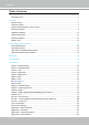
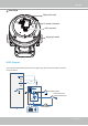
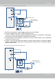
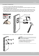
Table Of Contents
- Read Before Use
- Overview
- Hardware Installation
- Accessing the Network Camera
- Using VIVOTEK Recording Software
- Main Page
- Client Settings
- Configuration
- System > General settings
- System > Homepage layout
- System > Logs
- System > Parameters
- System > Maintenance
- Media > Image
- Media > Video
- ■ Smart stream III
- Media > Audio
- Network > General settings
- Network > Streaming protocols
- Network > DDNS
- Network > SNMP (Simple Network Management Protocol)
- Network > FTP
- Security > User accounts
- Security > HTTPS (Hypertext Transfer Protocol over SSL/TLS)
- Security > Access List
- PTZ > PTZ settings
- Event > Event settings
- Applications > Motion detection
- Applications > DI and DO
- Applications > Tampering detection
- Applications > Audio detection
- Applications > VADP (VIVOTEK Application Development Platform)
- Recording > Recording settings
- Local storage > SD card management
- Local storage > Content management
- Appendix

VIVOTEK
User's Manual - 8
DI-
DO+
DI+
DO-
Switch
External Device
External DC power
Wet contact with external DC power source to supply a relay.
NC
NO
Relay
DC
External AC power
with Protected Earth
AC
PE
PE
DC 0V
1. The DO+ pin provides 5V output voltage, and the max. load is 50mA.
2. The max. voltage for DO- pins is 30VDC (External power).
In order to control AC devices, the above diagram can be taken in consideration. The diagram
uses a relay to control the ON/OFF condition of the AC device.
3. An external relay can be triggered by using DO+ or by an external power source, depending
on the type of relay you use.
4. In case of using an individual relay (instead of using a relay module), for protection against
voltage or current spikes, a transient voltage suppression diode must be connected in parallel
with the inductive load.
DI-
DO+
DI+
DO-
Switch
External Device
Dry contact and using camera’s DO+ to supply a relay.
NC
NO
Relay
AC
External AC power
with Protected Earth
PE
PE