
User Manual
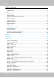
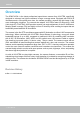
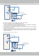
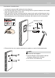
Table Of Contents
- Read Before Use
- Overview
- Hardware Installation
- Accessing the Network Camera
- Using VIVOTEK Recording Software
- Main Page
- Client Settings
- Configuration
- System > General settings
- System > Homepage layout
- System > Logs
- System > Parameters
- System > Maintenance
- Media > Image
- Media > Video
- ■ Smart stream III
- Media > Audio
- Network > General settings
- Network > Streaming protocols
- Network > DDNS
- Network > SNMP (Simple Network Management Protocol)
- Network > FTP
- Security > User accounts
- Security > HTTPS (Hypertext Transfer Protocol over SSL/TLS)
- Security > Access List
- PTZ > PTZ settings
- Event > Event settings
- Applications > Motion detection
- Applications > DI and DO
- Applications > Tampering detection
- Applications > Audio detection
- Applications > VADP (VIVOTEK Application Development Platform)
- Recording > Recording settings
- Local storage > SD card management
- Local storage > Content management
- Appendix

VIVOTEK
User's Manual - 10
Hardware Installation
Ø 9.5mm or 3/8”
1. Jot down the camera's MAC address for later reference.
2. The camera weighs 6kg. Select a rigid mounting location to prevent vibration to the camera.
Attach the alignment sticker to the wall.
3. Drill 4 pilot holes (9.5mm in diameter and 4cm deep) into the wall, and then hammer in the
threaded anchors. Note that you should hammer the anchors with hex nuts on them so that
the threaded poles will not be deformed! If preferred, drill another hole for routing cables.
4. Remove the hex nuts, washers, and leave one washer on each of the threaded poles.
0002D10766AD
SDXXXX
1. IO wires are user-supplied.
2. Avoid touching the circuit boards to prevent
damage by electro static discharge.
3. Use CAT5e, CAT6 cables only.
NOTE: