Product name: Network Camera (IP7151 / IP7152) Release Date: 2008/04/25 Manual Revision: 1.1 Web site: www.vivotek.com Email: technical@vivotek.com sales@vivotek.com Made in Taiwan. ©Copyright 2000-2007. All rights reserved -1www.vivotek.
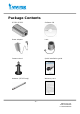
Before You Use This Product The use of surveillance devices may be prohibited by law in your country. The Network Camera is not only a high-performance web-ready camera but also can be part of a flexible surveillance system. It is the user’s responsibility to ensure that the operation of such devices is legal before installing this unit for its intended use. It is important to first verify that all contents received are complete according to the list in the "Package Contents" chapter.
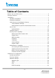
Table of Contents Before You Use This Product......................................................................2 Package Contents ....................................................................................6 Installation .............................................................................................7 Hardware installation..........................................................................7 Software installation..................................................................
WLAN Settings (IP7152 only)............................................................. 34 DDNS............................................................................................. 36 Access List ...................................................................................... 37 Audio and Video............................................................................... 38 Video Settings............................................................................ 38 Video orientation .......
Drive the digital output ............................................................... 93 Query status of the digital input ................................................... 94 Query status of the digital output ................................................. 95 Capture single snapshot .............................................................. 96 Account management ................................................................. 97 System logs......................................................
Package Contents IP7151/IP7152 Software CD Power adapter Lens Camera stand Quick installation guide Antenna (IP7152 only) Warranty card -6www.vivotek.
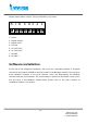
Installation In this manual, "User" refers to whoever has access to the Network Camera, and "Administrator" refers to the person who can configure the Network Camera and grant user access to the camera. Hardware installation the foregoing Package Contents. Depending on the user’s application, an Ethernet cable may be needed. The Ethernet cable should meet the specs of UTP Category 5 and not exceed 100 meters in length.
digital output device control. The pin definition is as below. 8 7 6 5 4 3 2 1 1: Power 2: Digital Output 3: Digital Input 4: Ground 5: AC 24V input 6: AC 24V input 7: RS-485 8: RS-485 + Software installation At the end of the hardware installation, users can use “Installation Wizard 2” program included in the product CDROM to find the location of the Network Camera. There may be many Network Cameras in the local network. Users can differentiate the Network Cameras with the serial number.
Once installation is complete, the Administrator should proceed to the next section "Initial access to the Network Camera" for necessary checks and configurations. Initial Access to the Network Camera Check Network Settings The Network Camera can be connected either before or immediately after software installation onto the Local Area Network. The Administrator should complete the network settings on the configuration page, including the correct subnet mask and IP address of gateway and DNS.
How to Use A PC with Windows operating system can use the Internet Explorer to connect to the Network Camera. A plug-in will be installed into the IE when it is connected for the first time. A PC with Linux operating system can connect to the camera using a browser like Firefox. It needs to install QuickTime first to view streaming. Authentication After opening the Web browser and typing in the URL of the Network Camera, a dialogue window pops up to request a username and password.
for permission to install a new plug-in for the Network Camera when the Internet Explorer. Permission request depends on the Internet security settings of the user’s PC or notebook. If the highest security level is set, the computer may prohibit any installation and execution attempt. This plug-in has been registered for certificate and is used to display the video in the browser. Users may click on to proceed.
Primary user’s capability Main Screen with Camera View The main page layout has two parts: Configuration functions: The camera can be configured using these user interfaces. Camera View: What the camera sees. Click on the configuration link to the left of the image window to enter the configuration page. Here is the layout in IE when it is MPEG-4 streaming. - 12 www.vivotek.
The function in JPEG will be a little different when it is JPEG streaming. Only digital zoom and record button are supported. - 13 www.vivotek.
Here is the layout in Firefox when it is MPEG-4 streaming. It uses QuickTime to streaming. - 14 www.vivotek.
Here is the layout in Firefox when it is JPEG streaming. - 15 www.vivotek.
Digital Zoom Click on the magnifier icon under the camera view then the digital zoom control panel will be shown. Uncheck “Disable digital zoom” and use the slider control to change the zoom factors. MP4 Recording Click on the red circle button on the plug-in to start video recording in MP4 file format. You can set the related options in client setting page. - 16 www.vivotek.
Snapshot Click on “Snapshot”, web browser will pop up a new window to show the snapshot. Users can point at the snapshot and click the right button of mouse to save it. Language Click on the language, all supported languages are shown in the drop-down list. The user can choose the different display language. - 17 www.vivotek.
Client settings There are four settings for the client side in IE. The first one is “Stream Options” for users to determine which stream to be streaming. This product supports dual-stream. Therefore, there are two streams to choose. The second one is “MPEG-4 Media Options” for users to determine which media to be streamed under MPEG-4 mode. The third one is “MPEG-4 Protocol Options” which allows choices on connection protocol between client and server.
some packets may be lost due to network burst traffic and images may be obscured. The UDP multicast protocol allows to save the bandwidth of server while serving multiple clients at the same time. The TCP protocol allows for less packet loss and produces a more accurate video display. The downside with this protocol is that the real-time effect is worse than that with the UDP protocol.
There is only one setting “Stream Options” for the client side in Firefox. User can choose to view stream1 and stream2. http:///clientset.html is the domain name or the original IP address of the Network Camera. Digital output Click on “ON”, the digital output of the Network Camera will be triggered. Or, clicking on “OFF” can let the digital output turn into normal state.
video quality, and at the lowest network bandwidth as possible. The three factors, “Maximum frame rate”, “Constant bit rate”, and “Fix quality” for MPEG-4 mode and “Maximum frame rate” and “Fix quality” for JPEG mode on the Audio and Video Configuration page, are correlative to allow for achieving the best performance possible. For Viewing by Mobile Phone Most 3GPP cell phone supports media streaming with MPEG4 video and GSM-AMR audio.
mentioned when viewing by mobile phone. For Best Real-time Video Images To achieve good real-time visual effect, the network bandwidth should be large enough to allow a transmission rate of greater than 20 image frames per second. If the broadband network is over 1 Mbps, set the “Constant bit rate” to 1000Kbps or 1200Kbps, or set “Fixed quality” at the highest quality. The maximum frame rate is 30.
Opening accounts for new users 1 2 3 Protect Network Camera by passwords The Network Camera is shipped without any password by default. That means everyone can access the Network Camera including the configuration as long as the IP address is known. It is necessary to assign a password if the Network Camera is 1 to enable protection. intended to be accessed by others. Type a new word twice in ○ This password is used to identify the administrator. Then add an account with user 2 .
Build a security application The Administrator can use the built-in motion detection to monitor any movement to perform many useful security applications. To upload the snapshots, users can choose either email, FTP, HTTP or Network storage according to user’s needs. All servers setting are in Server section on Application page. Refer to the definition section for detailed configuration. 1. Click on “Configuration” on homepage, 2. Click on “Motion detection” at the left column, 3.
z Check the server name set in Step 10 and select the media name set in Step 11. 13. Click on save to validate. Software revision upgrade Customers can obtain the up-to-date software from the web site of Vivotek. An easy-to-use Upgrade Wizard is provided to upgrade the Network Camera with just a few clicks. The upgrade function is opened to the Administrator only. To upgrade the system, follow the procedures below. 1. Download the firmware file named “xxx.pkg” from the appropriate product folder. 2.
Definitions in Configuration Only the Administrator can access system configuration. Each category in the left column will be explained in the following pages. The bold texts are the specific phrases on the Option pages. The Administrator may type the URL below the figure to directly enter the frame page of configuration. If the Administrator also wants to set certain options through the URL, read the reference appendix for details. http:///setup/system.
System parameters "Host name" The text displays the title at the top of the main page. “Turn off the LED indicator” Check this option to shut off the Status LED. It can prevent the camera’s operation being noticed. "Time zone" Adjust the time with that of the time-servers for local settings. "Keep current date and time" Click on this to reserve the current date and time of the Network Camera. An internal real-time clock maintains the date and time even when the power of the system is turned off.
Security settings “Root password” Change the Administrator’s password by typing in the new password identically in both text boxes. The typed entries will be displayed as asterisks for security purposes. After pressing , the web browser will ask the Administrator for the new password for access. “Add user” Type the new user's name and password and press to insert the new entry. The new user will be displayed in the user name list. There is a maximum of twenty user accounts.
http:///setup/security.html is the domain name or original IP address of the Network Camera. - 29 www.vivotek.
Network settings Any changes made on the Network type sectoin will restart the system in order to validate the changes. Make sure every field is entered correctly before clicking on . Network type “LAN” & “PPPoE” The default type is LAN. Select PPPoE if using ADSL "Get IP address automatically" & “Use fixed IP address” The default status is “Get IP address automatically”. This can be tedious having to perform software installation whenever the Network Camera starts.
“Enable UPnP presentation” Enable the UPnP camera short cut. “Enable UPnP port forwarding” Enable UPnP port forwarding. “PPPoE” If using the PPPoE interface, fill the following settings from ISP “User name” The login name of PPPoE account. “Password” The password of PPPoE account. “Confirm password” Input password again for confirmation. HTTP “Authentication” It supports basic and digest modes. “Http port” This can be other than the default Port 80.
“Access name for stream 2” This is the access URL of stream 2 for making connection from client software when the codec type is MPEG-4. Using rtsp:/// to make connection “RTSP port” This can be other than the default Port 554 “RTP port for video” The video channel port for RTP. It must be an even number. “RTCP port for video” The video channel port for RTCP. It must be the port number of video RTP plus 1. “RTP port for audio” The audio channel port for RTP. It must be even number.
http:///setup/network.html is the domain name or original IP address of the Network Camera. - 33 www.vivotek.
WLAN Settings (IP7152 only) “SSID” (Service Set Identifier), it is a name that identifies a wireless network. Access Points and wireless clients attempting to connect to a specific WLAN (Wireless Local Area Network) must use the same SSID. The default setting is default. Note: The maximum length of SSID is 32 single-byte characters and SSID can’t be any of “, <, > and space character.
“ASCII” is a code for representing English letters as numbers from 0-127 except “, <, > and space characters that are reserved. “Network Key” Entering a key in either hexadecimal or ASCII format. When selecting different key length, acceptable input length is listed as following: 64 bits key length: 10 Hex digits or 5 characters. 128 bites key length: 26 Hex digits or 13 characters. Note: When 22(“), 3C(<) or 3E(>) are input in network key, the key format can’t be changed to ASCII format.
DDNS “Enable DDNS” This option turns on the DDNS function. “Provider” The provider list contains four hosts that provide DDNS services. Please connect to the service provider’s website to make sure the service charges. “Host Name” If the User wants to use DDNS service, this field must be filled. Please input the hostname that is registered in the DDNS server. “Username/E-mail” The Username or E-mail field is necessary for logging in the DDNS server or notify the User of the new IP address.
Access List The access list is to control the access permission of clients by checking the client IP address. There are two lists for permission control: Allowed List and Denied List. Only those clients whose IP address is in the Allowed List and not in the Denied List can connect to the Video Server or Network Camera for receiving the audio/video streaming. Both Allowed List and Denied List consist of a list of IP ranges.
Audio and Video This product supports dual-stream. It provides two setting for video streams, but only one setting for audio. Video Settings “Video title” The text string can be displayed on video “Color” Select either for color or monochrome video display. “Power line frequency”, the fluorescent light will flash according to the power line frequency that depends on local utility. Change the frequency setting to eliminate uncomfortable flash image when the light source is only fluorescent light.
Choose “Constant bit rate” If the user wants to fix the bandwidth utilization regardless of the video quality, choose “Fixed quality” and select the desired bandwidth. The video quality may be poor due to the sending of maximal frame rate within the limited bandwidth when images are moving rapidly. Consequently, to ensure detailed video quality (quantization rate) regardless of the network, it will utilize more bandwidth to send the maximal frames when images change drastically.
http:///setup/audiovideo.htm is the domain name or original IP address of the Network Camera. - 40 www.vivotek.
Image Settings Click on this button to pop up another window to tune “Brightness”, “Contrast” and “Saturation” for video compensation. Each field has eleven levels ranged from -5 to +5. In “Brightness” and “Contrast” fields the value 0 indicates auto tuning. The user may press O.K; press to fine-tune the image. When the image is to set the image settings. Click on this to recall the original settings without incorporating the changes. - 41 www.vivotek.
Privacy Mask Click on the button to pop up another window to set privacy mask window. All users can not view the block under privacy mask window. “Enable privacy mask” Check this option to turn on privacy mask. Click on this button to add a new window. At most five windows can exist simultaneously. Use the mouse to click, hold, and drag the window frame to resize or the title bar to move. Click on the ‘x’ at the upper right-hand corner of the window to delete the window.
The following figure shows the screen when is clicked and the privacy mask is enabled. - 43 www.vivotek.
CCD Settings Click on “CCD Settings” button, the CCD settings window will pop up. “IRIS level” let users to adjust the aperture size of your auto iris lens. “AGC” - automatic gain control, enable this to do MAX AGC, otherwise NORMAL AGC is done. “AES” - auto electronic shutter, enable this will let CCD sensor adjust electronic shutter automatically. Disable this when auto iris lens is attached. “BLC” - back light compensation, enable this will help to identify objects in front of light source.
you can decide when to switch between “Day mode” and “Night mode” automatically. The user may press to fine-tune the image. When the image is O.K; press to set the CCD settings. Click on this to recall the original settings without incorporating the changes. Motion detection “Enable motion detection” Check this option to turn on motion detection. Click on this button to add a new window. At most three windows can exist simultaneously.
http:///setup/motion.htm - 46 www.vivotek.
Camera control In camera control page, if user configures “RS485 Settings” as “Disable”, it means the camera is fixed or doesn’t support Pan/Tilt/Zoom features. If user selects “RS485 Settings” as “PTZ camera”, the camera control setting functions will be enabled and the control panel will appear on permitted users’ main page. Users can configure their PTZ camera driver and control their camera in pan and tilt direction as well as zoom and focus.
The figure below is the layout when “PTZ camera” is checked. Users can configure the camera driver and RS485 port settings. - 48 www.vivotek.
Camera control panel doesn’t show up in `Fixed Camera’ mode If there is any PTZ camera attached, users should select the“RS485 Settings” as “PTZ camera”. Users have to configure the camera id, PTZ driver, and ports settings correctly. The ID is specific to the camera and necessary for multiple camera control. Please refer to the PTZ camera’s user manual for ID settings. The network camera has three built-in PTZ camera drivers, including DynaDome/SmartDOME, Lilin PIH-7x00, and Pelco D protocol.
Preset position Pan and Tilt Zoom Focus functions Newly added preset position will appear in this list. User can manage this list through adding and deleting Users can define a list of preset locations up to 20 through pan/tilt functions and zoom/focus functions. After setting up a preset location, users should give it a proper name, and those pre-defined locations will save into the preset location list and also show up in the homepage.
Custom command The network camera provides five more custom commands other than general pan, tilt, zoom and preset functions. Users can click on “Custom commands” and refer to the instruction manual of the attached device to setup frequently used functions. Please note that if “Custom camera” is selected as PTZ driver, user must configure the custom pan, tilt, zoom, and focus functions via “Custom Command” page. 1. Select Custom camera 3. Configure the PTZF functions 2.
Application There are three sections in application page. They are event, server and media. Click to pop a window to add a new item of event, server or media. Click to delete the selected item from event, server or media. Click on the item name to pop a window to edit it. There can be at most three events. There can be at most five server and five media configurations. User can know the event name, status, weekly and time schedule and trigger type in event section.
http:///setup/application.htm is the domain name or original IP address of the Network Camera. Event “Event name” The unique name for event “Enable this event” Check it to enable this event. “Priority” The event with higher priority will be executed first. “Delay second(s) before detecting next event” The delay to check next event. It is used in motion detection and digital input trigger type. There are four kinds of trigger supported.
“Sun” ~ “Sat” Select the days of the week to perform the event. “Time” show “Always” or input the time interval. If there are servers configured, the user can select them from “Server name”, too. “Trigger DO” Check it to trigger digital output for specific seconds when event is triggered. “Server name” Check it to sending the selected media when event is triggered. Server “Server name” The unique name for server There are four kinds of servers supported.
Here is setting for email server. “Sender email address” The email address of the sender “Recipient email address” The email address of the recipient “Server address” The domain name or IP address of the external email server. “User name” This granted user name on the external email server. “Password” This granted password on the external email server. Here is setting for FTP server. “Server address” The domain name or IP address of the external FTP server.
Media “Media name” The unique name for media There are three kinds of media. They are snapshot, video clip and system log. Here is setting for snapshot. “Source” The source of stream, stream1 or stream2. “Send Pre-event images” The number of pre-event images “Send Post-event images” The number of post-event images “File name prefix” The prefix name will be added on the file name of the snapshot images. “Add date and time suffix to file name” Check it to add timing information as file - 56 www.vivotek.
name suffix. Here is setting for video clip “Source” The source of stream, stream1 or stream2. “Pre-event recording” The interval of pre-event recording in seconds There are two limitations for video clip file. “Maximum duration” The maximal recording file duration in seconds “Maximum file size” The maximal file size would be generated. “File name prefix” The prefix name will be added on the file name of the video clip. Recording The Network camera supports recording on network storage.
recording item is the same as the one in application page. User can know the recording name, status, weekly and time schedule, stream source and destination of recording. There can be at most two recording entries. To do recording on network storage, please add network storage server in application page first. http:///setup/recording.htm is the domain name or original IP address of the Network Camera.
“File name prefix” The prefix name will be added on the file name of the recording. When click on the destination, a page appears listing all .mp4 files in that destination. User can select some files to delete or delete all files. System log The Network camera support log the system messages on remote server. The protocol is compliant to RFC 3164. If you have external Linux server with syslogd service, use “-r” option to turn on the facility for receiving log from remote machine.
Check “Enable remote log” and input the “IP address” and “port” number of the log server to enable the remote log facility. In the “Current log”, it displays the current system log file. The content of the log provides useful information about configuration and connection after system boot- up. http:///setup/syslog.htm is the domain name or original IP address of the Network Camera.
http:///setup/parafile.htm is the domain name or original IP address of the Network Camera. - 61 www.vivotek.
Maintenance Five actions can be selected. “Reboot system” Click the reboot button to restart system “Restore” Click it to restore all setting to factory default except setting in “Network type” in network page. “Factory default” Click on Factory default button on the configuration page to restore the factory default settings. Any changes made so far will be lost and the system will be reset to the initial factory settings.
http:///setup/maintain.htm is the domain name or original IP address of the Network Camera. - 63 www.vivotek.
Appendix A. Troubleshooting Status LED The following table lists the LED patterns in general.
B. URL commands of the Network Camera Overview For some customers who already have their own web site or web control application, Network Camera/Video server can be easily integrated through convenient URLs. This section specifies the external HTTP based application programming interface. The HTTP based camera interface provides the functionality to request a single image, to control camera functions (PTZ, output relay etc.) and to get and set internal parameter values.
returned data in a box. All data returned as HTTP formatted, i.e., starting with the string HTTP is line separated with a Carriage Return and Line Feed (CRLF) printed as \r\n. Return: HTTP/1.0 \r\n URL syntax examples are written with "Example:" in bold face followed by a short description and a light grey box with the example. Example: request a single snapshot image http://mywebserver/cgi-bin/viewer/video.
dido, camctrl, camera’s parameters except some privilege and operator 6 [admin] network options anonymous, viewer, Administrator’s access right can fully control the dido, camctrl, camera’s operation. operator, admin 7 N/A Internal parameters. Unable to be changed by any external interface. Get server parameter values Note: The access right depends on the URL directory. Method: GET/POST Syntax: http:///cgi-bin/anonymous/getparam.
HTTP/1.0 200 OK\r\n Content-Type: text/html\r\n Context-Length: \r\n \r\n where is =\r\n [] is the actual length of content. Example: request IP address and it’s response Request: http://192.168.0.123/cgi-bin/admin/getparam.cgi?network_ipaddress Response: HTTP/1.0 200 OK\r\n Content-Type: text/html\r\n Context-Length: 33\r\n \r\n network.ipaddress=192.168.0.
[&=…][&update=] [&return=] http:///cgi-bin/operator/setparam.cgi? = [&=…][&update=] [&return=] http:///cgi-bin/admin/setparam.
Only the parameters that you set and readable will be returned. Example: Set the IP address of server to 192.168.0.123 Request: http://myserver/cgi-bin/admin/setparam.cgi?network_ipaddress=192.168.0.123 Response: HTTP/1.0 200 OK\r\n Content-Type: text/html\r\n Context-Length: 33\r\n \r\n network.ipaddress=192.168.0.
, , … blank A blank string everything inside <> As description NOTE: The camera should prevent to restart when parameter changed. Group: system NAME VALUE SECURITY DESCRIPTION (get/set) hostname string[40] 1/6 host name of server ledoff 6/6 turn on(0) or turn off(1) all led indicators date , 6/6 Current date of system. Set to keep, ‘keep’ keeping date unchanged. auto Set to ‘auto’ to use NTP to synchronize date.
San_Francisco, Vancouver -280: GMT-07:00 Mountain Time, Denver -281: GMT-07:00 Arizona -240: GMT-06:00 Central America, Central Time, Mexico City, Saskatchewan -200: GMT-05:00 Eastern Time, New York, Toronto -201: GMT-05:00 Bogota, Lima, Quito, Indiana -160: GMT-04:00 Atlantic Time, Canada, Caracas ,La Paz, Santiago -140: GMT-03:30 Newfoundland -120: GMT-03:00 Brasilia, Buenos Aires, Georgetown, Greenland -80: GMT-02:00 Mid-Atlantic -40: GMT-01:00 Azores, Cape_Verde_IS.
81: GMT 02:00 Cairo 82: GMT 02:00 Lebanon, Minsk 83: GMT 02:00 Israel 120: GMT 03:00 Baghdad, Kuwait, Riyadh, Moscow, St.
400: GMT 10:00 Brisbane, Canberra, Melbourne, Sydney, Guam, Vladivostok 440: GMT 11:00 Magadan, Solomon Is., New Caledonia 480: GMT Wellington, 12:00 Fiji, Aucklan, Kamchatka, Marshall Is. 520: GMT 13:00 Nuku'Alofa updateinterval 6/6 0, 0 to Disable automatic time 3600, adjustment, otherwise, it 86400, means the seconds between 604800, NTP automatic update interval. 2592000 restore reset 7/6 0, Restore the system parameters
firmwareversion string[40] 0/7 The version of firmware, including model, company, and version number in the format language_default string[16] 0/7 Default webpage language.
inactive status Group: security NAME VALUE SECURITY DESCRIPTION (get/set) user_i0_name string[64] 6/7 User’s name of root user_i<1~20>_name string[64] 6/7 User’s name user_i0_pass string [64] 6/6 Root’s password user_i<1~20>_pass string [64] 7/6 User’s password user_i0_privilege admin 6/7 Root’s privilege user_i<1~20>_ viewer, 6/6 User’s privilege.
Subgroup of network: ftp NAME VALUE SECURITY DESCRIPTION (get/set) port 21, 6/6 local ftp server port SECURITY DESCRIPTION 1025~65535 Subgroup of network: http NAME VALUE (get/set) port 80, 1025 ~ 6/6 HTTP port 65535 alternateport 1025~65535 6/6 Alternative HTTP port authmode basic, 1/6 HTTP authentication mode 1/6 Http server push access name digest s0_accessname string[32] for stream 1 s1_accessname string[32] 1/6 Http server push access name for stream 2 Subgroup of netwo
alwaysmulticast 4/4 Enable always multicast ipaddress 4/4 Multicast IP address videoport 1025 ~ 65535 4/4 Multicast video port audioport 1025 ~ 65535 4/4 Multicast audio port ttl 1 ~ 255 4/4 Mutlicast time to live value SECURITY DESCRIPTION Subgroup of network: rtp NAME VALUE (get/set) videoport 1025 ~ 65535 6/6 video channel port for RTP audioport 1025 ~ 65535 6/6 audio channel port for RTP Subgroup of network: pppoe NAME VALUE SECURITY DESCRIPTION (ge
255 Group: videoin NAME VALUE SECURITY DESCRIPTION (get/set) cmosfreq 50, 60 4/4 CMOS frequency whitebalance auto, 4/4 auto, auto white balance indoor, indoor, 3200K fluorescent, fluorescent, 5500K outdoor outdoor, > 5500K Group: videoin_c<0~(n-1)> for n channel products, m is stream number NAME VALUE SECURITY DESCRIPTION (get/set) color 0, 1 4/4 0 =>monochrome 1 => color flip 4/4 flip the image mirror 4/4 mirror the image ptzstatus 1/7 An 3
1(support) Bit 5 => operation.
2000000, 3000000, 4000000 s<0~(m-1)>_maxfr 1, 2, 3, 5, 10, 4/4 ame set maximum frame rate in fps 15, 20, 25, 30 (only for NTSC or 60Hz CMOS) s<0~(m-1)>_forcei 1 7/6 Force I frame Group: audioin_c<0~(n-1)> for n channel products NAME VALUE SECURITY DESCRIPTION (get/set) source micin, 4/4 linein micin => use external microphone input linein => use line input, i.e.
10200, 12200 Group: image_c<0~(n-1)> for n channel products NAME VALUE SECURITY DESCRIPTION (get/set) brightness -5 ~ 5 4/4 Adjust brightness of image according to mode settings. saturation -5 ~ 5 4/4 Adjust saturation of image according to mode settings. contrast -5 ~ 5 4/4 Adjust contrast of image according to mode settings. hue -5 ~ 5 4/4 Adjust hue of image according to mode settings.
Group: ddns NAME VALUE SECURITY DESCRIPTION (get/set) enable 6/6 Enable or disable the dynamic dns. provider Safe100, 6/6 Safe100 => safe100.net DyndnsDynami DyndnsDynamic => c, dyndns.org (dynamic) DyndnsCustom, DyndnsCustom => dyndns.org TZO, (custom) DHS, TZO => tzo.com DynInterfree, DHS => dhs.org PeanutHull, DynInterfree CustomSafe100 =>dyn-interfree.
Group: upnpportforwarding NAME VALUE SECURITY DESCRIPTION (get/set) enable 6/6 Enable or disable the UPNP port forwarding service. upnpnatstatus 0~3 6/7 The status of UpnP port forwarding, used internally.
win_i<0~4>_enable 4/4 Enable the privacy mask window win_i<0~4>_name string[14] 4/4 The name of privacy mask window win_i<0~4>_left 0 ~ 320/352 4/4 Left coordinate of window of window position. win_i<0~4>_top 0 ~ 240/288 4/4 Top coordinate position.
integer> nmediastream nvideosetting channel naudiosetting number of video settings per channel nuart number of media stream per number of audio settings per channel 0, 0/7 number of UART interface 0/7 indicate whether to support ptzenabled < boolean > PTZ control protocol_https < boolean > 0/7 indicate whether to support http over SSL protocol_rtsp < boolean > 0/7 indicate whether to support r
1 => Progressive CCD 2 => CMOS videoin_resolution 0/7 indicate whether to support acoustic echo cancellation audio_extmic 0/7 indicate whether to support external microphone inpu
codec types separaters by comma) camctrl_httptunnel 0/7 Indicate whether to support the http tunnel for camera control uart_httptunnel 0/7 Indicate whether to support the http tunnel for uart transfer transmission_mode 0/7 Tx, Indicate what kind Rx, transmission Both machine used. TX: server, Rx: receiver mode of box, the Both: DVR?.
enable 0, 1 6/6 To enable or disable this event. priority 0, 1, 2 6/6 Indicate the priority of this event. “0” indicates low priority. “1” indicates normal priority. “2” indicates high priority. delay 1~999 6/6 Delay seconds before detect next event. trigger boot, 6/6 Indicate the trigger condition. di, “boot” indicates system boot. motion, “di” indicates digital input. seq, “motion” indicates video motion detection. “seq” indicates periodic condition.
weekday 6/6 Indicate which weekday is scheduled. One bit represents one weekday. The bit0 (LSB) indicates Saturday. The bit1 indicates Friday. The bit2 indicates Thursday. The bit3 indicates Wednesday. The bit4 indicates Tuesday. The bit5 indicates Monday. The bit6 indicates Sunday. For example, to detect events on Friday and Sunday, set weekday as 66. begintime hh:mm 6/6 Begin time of weekly schedule. endtime hh:mm 6/6 End time of weekly schedule. (00:00 ~ 24:00 means always.
http_username string[64] 6/6 The username to login in the server. http_passwd string[64] 6/6 The password of the user. ftp_address string[128] 6/6 The ftp server address ftp_username string[64] 6/6 The username to login in the server. ftp_passwd string[64] 6/6 The password of the user. ftp_port 0~65535 6/6 The port to connect the server. ftp_location string[128] 6/6 The location to upload or store the media. ftp_passive 0, 1 6/6 To enable or disable the passive mode.
snapshot_source 6/6 Indicate the source of media stream. 0 means the first stream. 1 means the second stream and etc. snapshot_prefix string[16] 6/6 Indicate the prefix of the filename. snapshot_datesuffix 0, 1 6/6 To add date and time suffix to filename or not. 1 means to add date and time suffix. 0 means not to add it. snapshot_preevent 0~7 6/6 It indicates the number of pre-event images. snapshot_postevent 0~7 6/6 The number of post-event images.
source 6/6 Indicate the source of media stream. 0 means the first stream. 1 means the second stream and etc. weekday 6/6 Indicate which weekday is scheduled. One bit represents one weekday. The bit0 (LSB) indicates Saturday. The bit1 indicates Friday. The bit2 indicates Thursday. The bit3 indicates Wednesday. The bit4 indicates Tuesday. The bit5 indicates Monday. The bit6 indicates Sunday. For example, to detect events on Friday and Sunday, set weekday as 66.
triggered state. PARAMETER VALUE DESCRIPTION do 0, 1 0 – inactive, normal state 1 – active, triggered state return Redirect to the page after the parameter is assigned. The can be a full URL path or relative path according the the current path. If you omit this parameter, it will redirect to an empty page. Example: Drive the digital output 1 to triggered state and redirect to an empty page http://myserver/cgi-bin/dido/setdo.
[di3=]\r\n where can be 0 or 1. Example: Query the status of digital input 1 Request: http://myserver/cgi-bin/dido/getdi.cgi?di1 Response: HTTP/1.0 200 OK\r\n Content-Type: text/plain\r\n Content-Length: 7\r\n \r\n di1=1\r\n Query status of the digital output Note: This request requires the privilege of viewer. Method: GET/POST Syntax: http:///cgi-bin/dido/getdo.cgi?[do0][&do1][&do2][&do3] If no parameter is specified, all the status of digital output will be returned.
[do3=]\r\n where can be 0 or 1. Example: Query the status of digital output 1 Request: http://myserver/cgi-bin/dido/getdo.cgi?do1 Response: HTTP/1.0 200 OK\r\n Content-Type: text/plain\r\n Content-Length: 7\r\n \r\n do1=1\r\n Capture single snapshot Note: This request require normal user privilege Method: GET/POST Syntax: http:///cgi-bin/viewer/video.
JPEG format. The size and quality of image will be set according to the video settings on the server. Return: HTTP/1.0 200 OK\r\n Content-Type: image/jpeg\r\n [Content-Length: \r\n] Account management Note: This request requires administrator privilege Method: GET/POST Syntax: http:///cgi-bin/admin/editaccount.
userpass The password of new user to add or that of old user to modify. The default value is an empty string. privilege return The privilege of user to add or to modify. viewer viewer’s privilege operator operator’s privilege admin administrator’s privilege Redirect to the page after the parameter is assigned. The can be a full URL path or relative path according the the current path.
Upgrade firmware Note: This request requires administrator privilege Method: POST Syntax: http:///cgi-bin/admin/upgrade.cgi Post data: fimage=[&return=]\r\n \r\n Server will accept the upload file named to be upgraded the firmware and return with if indicated. IP filtering Note: This request requires administrator access privilege Method: GET/POST Syntax: http:///cgi-bin/admin/ipfilter.
adddeny Add a set of deny IP address range to server. Start and end parameters must be specified. If the index parameter is specified, it will try to add starting from index position. deleteallow Remove a set of allow IP address range from server. If start and end parameters are specified, it will try to remove the matched IP address. If index is specified, it will try to remove the address from given index position. [start, end] parameters have higher priority then the [index] parameter.
“n” is the channel number and “m” is the stream number. You can get the SDP by HTTP or just describe by RTSP protocol directly. For detailed streaming protocol, please refer to “control signaling” and “data format” documents. - 101 www.vivotek.
C. Technical specifications System and Hardware Security z CPU: VVTK-1000 SoC z Flash: 8MB z RAM: 64MB z IP address filtering z Lens: CS-mount, 2.9~8.2mm Vari-focal, auto-iris z Wireless: WEP, WPA-PSK, WPA2 (IP7152) z Angle of view: 95 ° ~ 35.6 ° z IR Corrected Power z Image sensor: 1/4”, Progressive scan CCD sensor z 12V DC with VGA resolution z 802.3af compliant power over Ethernet z protection (horizontal) z Shutter time: 1/30 sec. to 1/15000 sec.
z MJPEG streaming over HTTP Viewing System Requirements z Supports 3GPP mobile surveillance z OS: Microsoft Windows 2000/XP z Browser: Internet Explorer 5.x or above z Cellphone: 3GPP player Image settings z Adjustable image size, quality, and Bit-rate z Real Player 10.5 z Time stamp and text caption overlay z Quick Time 6.5 z Flip & mirror z Packet Video Player 3.
Technology License Notice MPEG-4 AAC Technology THIS PRODUCT IS LICENSED UNDER THE MPEG-4 AAC AUDIO PATENT LICENSE. THIS PRODUCT MAY NOT BE DECOMPILED, REVERSE-ENGINEERED OR COPIED, EXCEPT REGARD TO PC SOFTWARE, YOU MAY MAKE SINGLE COPIES FOR ARCHIVAL PURPOSES. FOR MORE INFORMATION, PLEASE REFER TO HTTP://WWW.VIALICENSING.COM.
Electromagnetic Compatibility (EMC) This device compiles with FCC Rules Part 15. Operation is subject to the following two conditions. • This device may not cause harmful interference, and • This device must accept any interference received, including interference that may cause undesired operation. USA - This equipment has been tested and found to comply with the limits for a Class B digital device, pursuant to Part 15 of the FCC Rules.