
User Manual
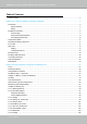
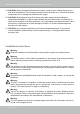
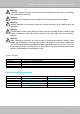
Table Of Contents
- Revision History
- Chapter One Hardware Installation and Initial Configuration
- Chapter Two VAST2 Software Configuration and Management
- Log in
- Introducing VAST2
- Charged Add-on Features
- Installation Option - OpenVPN
- Chapter 2-1 Basics: Control and Elements
- Hot Keys
- View Cell Elements
- VAST Server and Client Components
- Minimum System Requirements
- Chapter 2-2 Starting Up
- 2-2-1. Selecting Devices
- 2-2-2. Recording Options
- 2-2-3. Storage
- 2-2-4. Starting Up - Main Page
- 2-2-5. Saving a View
- 2-2-6. Add More Live Views
- 2-2-7. Save Your Preferences
- 2-2-8. Customizable Layout
- 2-2-9. Dashboard
- 2-2-10. E-Map
- Placing DI/DO Devices
- Configuring Google Map and GPS
- 2-2-11. Event Search
- 2-2-12. PTZ Control
- 2-2-13. Playback
- 2-2-14. Alarm
- 2-2-15. Search Panel
- 2-2-16. Smart search
- 2-2-17. Tour
- 2-2-18. Thumbnail search
- Chapter 3 Applications:
- 3-1. I/O DI/DO Devices: IO Box and Related Configuration
- Configuring I/O Box DI/DO as a Trigger or Action in Alarm
- 3-2. Configuring Redundant Servers - Failover
- Failover Configuration Process
- 3-3. VCA (Video Content Analysis)
- 3-4. VAST Software License
- Updating Licenses for VAST on Virtual Machines
- Reminders for VAST Software License
- Chapter 4 Settings:
- 4-1. Settings > System > Preferences
- 4-2. Settings > Device > Cameras
- 4-3. Logical Folders
- 4-4. Settings > Recording > Recording Options
- 4-5. Settings > Recording > Backup
- Storage
- 4-6. Settings > Device > Sites
- 4-7. Settings > Device > POS
- 4-8. Settings > Device > Local DB
- 4-9. Settings > System > SMTP
- 4-10. Settings > IO Box and Related Configuration
- 4-11. Settings > User Management
- Add a New User Account - Windows AD Account
- Appendix A: VAST Service Control Tool
- Appendix B: Matrix
- Appendix C: Joystick Support
- Appendix D: Upload Device Pack
- Appendix E Database Merge Function

VIVOTEK - A Leading Provider of Multimedia Communication Solutions
User's Manual - 9
Warning:
Hazardous voltage or energy is present on the backplane when the system is operating.
Use caution when servicing.
Warning:
Installation of the equipment must comply with local and national electrical codes.
Warning:
Ultimate disposal of this product should be handled according to all national laws and
regulations.
Warning:
The fans might still be turning when you remove the fan assembly from the chassis. Keep
fingers,screwdrivers, and other objects away from the openings in the fan assembly’s
housing.
Warning:
When installing the product, use the provided or designated connection cables, power
cables and AC adaptors. Using any other cables and adaptors could cause a malfunction
or a fire.Electrical Appliance and Material Safety Law prohibits the use of UL or CSA -cer-
tified cables (that have UL/CSA shown on the code) for any other electrical devices than
products designated by the manufacturer only.
Power Supply
Watt 550W max. (80+ Gold, PFC) (1+1 Redundant 2U)
Input rating 100 ~ 240 Vac ~ 6.9A-2.8A, 50-60Hz
Output voltage +5 VSB @ 2.5 A, +12 V @ 45A
Minimum load +12V @ 0.5 A
Safety UL/TUV/CCC
Environmental Specications
Environment Operating Non-operating
Temperature 5 ~ 35°C (32 ~ 104°F) --40 ~ 70°C (-40 ~ 158°F)
Humidity 10 ~ 95% @ 40°C, non-condensing 10 ~ 95% @ 60°C, non-condensing
Vibration 0.5 G rms 2 G
Shock 10 G with 11 ms duration, half sine wave
Safety CE compliant