
User Manual
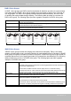
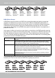
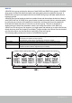
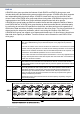
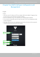
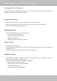
Table Of Contents
- Revision History
- Chapter One Hardware Installation and Initial Configuration
- Chapter Two VAST2 Software Configuration and Management
- Log in
- Introducing VAST2
- Charged Add-on Features
- Installation Option - OpenVPN
- Chapter 2-1 Basics: Control and Elements
- Hot Keys
- View Cell Elements
- VAST Server and Client Components
- Minimum System Requirements
- Chapter 2-2 Starting Up
- 2-2-1. Selecting Devices
- 2-2-2. Recording Options
- 2-2-3. Storage
- 2-2-4. Starting Up - Main Page
- 2-2-5. Saving a View
- 2-2-6. Add More Live Views
- 2-2-7. Save Your Preferences
- 2-2-8. Customizable Layout
- 2-2-9. Dashboard
- 2-2-10. E-Map
- Placing DI/DO Devices
- Configuring Google Map and GPS
- 2-2-11. Event Search
- 2-2-12. PTZ Control
- 2-2-13. Playback
- 2-2-14. Alarm
- 2-2-15. Search Panel
- 2-2-16. Smart search
- 2-2-17. Tour
- 2-2-18. Thumbnail search
- Chapter 3 Applications:
- 3-1. I/O DI/DO Devices: IO Box and Related Configuration
- Configuring I/O Box DI/DO as a Trigger or Action in Alarm
- 3-2. Configuring Redundant Servers - Failover
- Failover Configuration Process
- 3-3. VCA (Video Content Analysis)
- 3-4. VAST Software License
- Updating Licenses for VAST on Virtual Machines
- Reminders for VAST Software License
- Chapter 4 Settings:
- 4-1. Settings > System > Preferences
- 4-2. Settings > Device > Cameras
- 4-3. Logical Folders
- 4-4. Settings > Recording > Recording Options
- 4-5. Settings > Recording > Backup
- Storage
- 4-6. Settings > Device > Sites
- 4-7. Settings > Device > POS
- 4-8. Settings > Device > Local DB
- 4-9. Settings > System > SMTP
- 4-10. Settings > IO Box and Related Configuration
- 4-11. Settings > User Management
- Add a New User Account - Windows AD Account
- Appendix A: VAST Service Control Tool
- Appendix B: Matrix
- Appendix C: Joystick Support
- Appendix D: Upload Device Pack
- Appendix E Database Merge Function

VIVOTEK - A Leading Provider of Multimedia Communication Solutions
User's Manual - 53
RAID 00 Drive Groups
A RAID 00 drive group is a spanned drive group that creates a striped set from a series of
RAID0 drive groups. A RAID00 drive group does not provide any data redundancy, but, along
with the RAID0 drive group, does oer the best performance of any RAID level. A RAID00 drive
group breaks up data into smaller segments and then stripes the data segments across each
drive in the drive groups. The size of each data segment is determined by the stripe size. A
RAID00 drive group oers high bandwidth.
Uses Provides high data throughput, especially for large les.Any environment that does not
require fault tolerance.
Strong points Provides increased data throughput for large les.
No capacity loss penalty for parity.
Weak points Does not provide fault tolerance or high bandwidth.
All data lost if any drive fails.
Drives 2 through 256
NOTE
RAID level 00 is not fault tolerant. If a drive in a RAID 0 drive group fails, the entire virtual drive (all drives
associated with the virtual drive) fails.
By breaking up a large le into smaller segments, the controller can use both SAS drives and
SATA drives to read or write the le faster. A RAID00 drive group involves no parity calculations
to complicate the write operation. This situation makes the RAID00 drive group ideal for
applications that require high bandwidth but do not require fault tolerance. The following table
provides an overview of the RAID00 drive group. The following gure provides a graphic
example of a RAID 00 drive group.