
User Manual
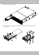
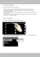
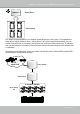
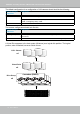
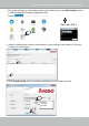
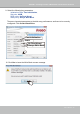
Table Of Contents
- Revision History
- Chapter One Hardware Installation and Initial Configuration
- Chapter Two VAST2 Software Configuration and Management
- Log in
- Introducing VAST2
- Charged Add-on Features
- Installation Option - OpenVPN
- Chapter 2-1 Basics: Control and Elements
- Hot Keys
- View Cell Elements
- VAST Server and Client Components
- Minimum System Requirements
- Chapter 2-2 Starting Up
- 2-2-1. Selecting Devices
- 2-2-2. Recording Options
- 2-2-3. Storage
- 2-2-4. Starting Up - Main Page
- 2-2-5. Saving a View
- 2-2-6. Add More Live Views
- 2-2-7. Save Your Preferences
- 2-2-8. Customizable Layout
- 2-2-9. Dashboard
- 2-2-10. E-Map
- Placing DI/DO Devices
- Configuring Google Map and GPS
- 2-2-11. Event Search
- 2-2-12. PTZ Control
- 2-2-13. Playback
- 2-2-14. Alarm
- 2-2-15. Search Panel
- 2-2-16. Smart search
- 2-2-17. Tour
- 2-2-18. Thumbnail search
- Chapter 3 Applications:
- 3-1. I/O DI/DO Devices: IO Box and Related Configuration
- Configuring I/O Box DI/DO as a Trigger or Action in Alarm
- 3-2. Configuring Redundant Servers - Failover
- Failover Configuration Process
- 3-3. VCA (Video Content Analysis)
- 3-4. VAST Software License
- Updating Licenses for VAST on Virtual Machines
- Reminders for VAST Software License
- Chapter 4 Settings:
- 4-1. Settings > System > Preferences
- 4-2. Settings > Device > Cameras
- 4-3. Logical Folders
- 4-4. Settings > Recording > Recording Options
- 4-5. Settings > Recording > Backup
- Storage
- 4-6. Settings > Device > Sites
- 4-7. Settings > Device > POS
- 4-8. Settings > Device > Local DB
- 4-9. Settings > System > SMTP
- 4-10. Settings > IO Box and Related Configuration
- 4-11. Settings > User Management
- Add a New User Account - Windows AD Account
- Appendix A: VAST Service Control Tool
- Appendix B: Matrix
- Appendix C: Joystick Support
- Appendix D: Upload Device Pack
- Appendix E Database Merge Function

VIVOTEK - A Leading Provider of Multimedia Communication Solutions
22 - User's Manual
Connecting Interfaces
Refer to page 13 for the interface connections.
1. Make sure all cameras have been properly installed, either they are powered by 12V
power lines or using one or several PoE switches or mid-spans. Refer to the cameras'
documentation for details.
2. Connect all other interfaces to USB mouse/keyboard, one or two monitors, and audio input/
output devices.
3. Make sure you connect both power supplies to power mains. An alarm will be sounded if you
connect only 1 of the power supplies.
Initial Conguration
1. Power up the system by pressing the power on button.
2. Skip the BIOS screens and select Enter NVR at the selection screen. The system will start.
Wait for the start-up process to complete.
0 Enter NVR
1 Restore to default
2 Reboot
3 Shutdown
Enter