
User Manual
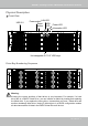
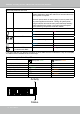

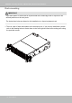
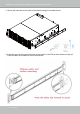
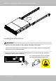
Table Of Contents
- Revision History
- Chapter One Hardware Installation and Initial Configuration
- Chapter Two VAST2 Software Configuration and Management
- Log in
- Introducing VAST2
- Charged Add-on Features
- Installation Option - OpenVPN
- Chapter 2-1 Basics: Control and Elements
- Hot Keys
- View Cell Elements
- VAST Server and Client Components
- Minimum System Requirements
- Chapter 2-2 Starting Up
- 2-2-1. Selecting Devices
- 2-2-2. Recording Options
- 2-2-3. Storage
- 2-2-4. Starting Up - Main Page
- 2-2-5. Saving a View
- 2-2-6. Add More Live Views
- 2-2-7. Save Your Preferences
- 2-2-8. Customizable Layout
- 2-2-9. Dashboard
- 2-2-10. E-Map
- Placing DI/DO Devices
- Configuring Google Map and GPS
- 2-2-11. Event Search
- 2-2-12. PTZ Control
- 2-2-13. Playback
- 2-2-14. Alarm
- 2-2-15. Search Panel
- 2-2-16. Smart search
- 2-2-17. Tour
- 2-2-18. Thumbnail search
- Chapter 3 Applications:
- 3-1. I/O DI/DO Devices: IO Box and Related Configuration
- Configuring I/O Box DI/DO as a Trigger or Action in Alarm
- 3-2. Configuring Redundant Servers - Failover
- Failover Configuration Process
- 3-3. VCA (Video Content Analysis)
- 3-4. VAST Software License
- Updating Licenses for VAST on Virtual Machines
- Reminders for VAST Software License
- Chapter 4 Settings:
- 4-1. Settings > System > Preferences
- 4-2. Settings > Device > Cameras
- 4-3. Logical Folders
- 4-4. Settings > Recording > Recording Options
- 4-5. Settings > Recording > Backup
- Storage
- 4-6. Settings > Device > Sites
- 4-7. Settings > Device > POS
- 4-8. Settings > Device > Local DB
- 4-9. Settings > System > SMTP
- 4-10. Settings > IO Box and Related Configuration
- 4-11. Settings > User Management
- Add a New User Account - Windows AD Account
- Appendix A: VAST Service Control Tool
- Appendix B: Matrix
- Appendix C: Joystick Support
- Appendix D: Upload Device Pack
- Appendix E Database Merge Function

VIVOTEK - A Leading Provider of Multimedia Communication Solutions
User's Manual - 11
Physical Description
Front View
Power switch
Reset
button
USB 3.0
LAN LED
Power LED
HDD
LED
Information LED
Hot-swappable 2.5”/3.5” HDD trays
2
1
0
1
2
3
4
5
6
7
8
9
10
11
12
13
14
15
Drive Bay Numbering Sequence
Warning:
Knowing the correct positions of hard drives is very important. For example, if a hard
drive fails in a RAID5 Virtual Drive, you can initialize a rebuild by locating and replacing
the failed drive. If you replace the wrong drive, it means that you have 1 failed drive and
another mistakenly failed drive. Having 2 failed drives in a RAID5 configuration renders
all data inaccessible. All data in the RAID5 Virtual Drive will be lost.