
User`s guide

Test Results
© 2008 Microchip Technology Inc. DS70320B-page 95
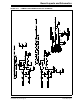
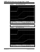
B.2 DYNAMIC LOAD RESPONSE
Dynamic load response is measuring the under/overshoot voltage and settling time of
the output voltage when performing a load step. The SMPS AC/DC Reference Design
has the following load step parameters when the outputs are loaded individually:
• 12V full load step of 30A
• 5V full load step of 23A
• 3.3V full load step of 69A
When the Single-Phase and Multi-Phase converters are loaded simultaneously, the
following are the max load steps:
• 5V full load step of 23A
• 3.3V full load step of 56A
The load response of each unit is tested with the following load steps with a maximum
slew rate of 1A/us:
• 0-15A and 15-0A (for the 12V output)
• 0-35A and 35-0A (for the 3.3V output)
• 0-12A and 12-0A (for the 5V output)
B.2.1 Test Procedure
1. Ensure that the system is off and that all probes are disconnected.
2. Connect a programmable DC load to any one of the three outputs.
3. Connect the oscilloscope probe across the output terminals with the DC load.
4. Connect the current probe to one of the load cables making sure of the direction
of current flow.
5. Set up the oscilloscope for a single capture and trigger on the current probe on
either edge and set the oscilloscope channel for AC coupling.
6. Perform the load steps and measure the settling time and under/overshoot
voltage.
7. Turn off the system and disconnect all probes.
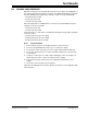
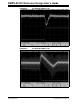
Figure B-3 through Figure B-8 show the dynamic load response and settling time with
50% load steps.