
User`s guide


SMPS AC/DC REFERENCE
DESIGN USER’S GUIDE
© 2008 Microchip Technology Inc. DS70320B-page 93
Appendix B. Test Results
This appendix provides information on the test procedures and results for the SMPS
AC/DC Reference Design.
The following equipment was used to test the SMPS AC/DC Reference Design:
• Programmable DC Load (or resistive load)
• Two- or Four-Channel Oscilloscope (100 MHz or higher)
• Current probe and Differential probe
• Programmable AC Source, or Variac, or AC Power Cord
• Power Meter
• True RMS Multimeter
B.1 SOFT-START AND OVERSHOOT
The SMPS AC/DC Reference Design has soft-start routines implemented for the PFC
Boost converter, ZVT converter, Single-Phase and Multi-Phase Buck converters. The
soft-start routines eliminate in-rush current, eliminates overshoot and provides control
of the output voltages during start-up. The soft-start scheme is sequenced as follows:
• The PFC Boost converter ramps to 420V,
• the ZVT converter ramps to 12V,
• the Single-Phase Buck converter ramps to 5V,
• and then the Multi-Phase converter ramps to 3.3V.
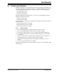
B.1.1 Test Procedure
1. Ensure that the system is off and that all probes are disconnected.
2. Connect the oscilloscope probes across the output terminals (J2, J4, and J17).
3. Set up the oscilloscope for normal trigger mode and on the rising edge of the
scope connected to (J2) with a time scale equal to 100 ms or greater. Move the
trigger start point to 200 ms.
4. Power on the unit and observe the soft-start.
5. Turn off the system and connect a programmable DC load to any single output
or to the 5V and 3.3V outputs simultaneously.
6. Power on the unit and observe the soft-start.
7. Turn off the system and disconnect all probes.
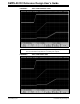
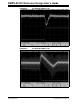
Figure B-1 demonstrates the soft-start sequence for the ZVT converter and the
Single-Phase and Multi-Phase converters.
Figure B-2 demonstrates the soft-start sequence with the Single-Phase and
Multi-Phase outputs loaded (5V @ 23A, 3.3V @ 35A).