
User`s guide

SMPS AC/DC Reference Design User’s Guide
DS70320B-page 72 © 2008 Microchip Technology Inc.
4.2 SYSTEM OPERATION
4.2.1 System Power-Up
Once the input and output connections as described in Section 4.1.4 “System
Connections” are completed, the mains voltage can be applied to the SMPS AC/DC
Reference Design.
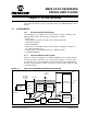
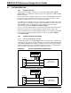
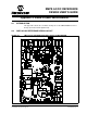
There are three power-on indicator LEDs on the system. One LED (D38) on the power
board near the AC input terminals, and two more on the control board (one on the
primary side (LED1), and one on the secondary side (LED2)).
There will be a short delay before the 12V, 5V, and 3.3V outputs are ON because of the
soft-start routines and output sequencing scheme implemented on each stage of the
SMPS AC/DC Reference Design. Details of the soft-start routine and output
sequencing are provided in Chapter 3. “Software Design”.
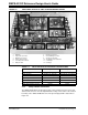
As soon as the 12V output is ON, the cooling fan mounted on the lid will start running.
LEDs are provided near each output terminal to indicate that the output is ON.
Faults are indicated on the control board with two LEDs (one on the primary side (D34)
and one on the secondary side (D33)). Details of faults are provided in Chapter
3. “Software Design”.
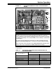
4.2.2 System Evaluation and Testing
4.2.2.1 INPUT PERFORMANCE TESTING
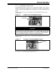
The input specifications of the SMPS AC/DC Reference Design can be tested by using
a power meter. The voltage is measured directly across the Live and Neutral terminals
on the SMPS AC/DC Reference Design. The input current is measured by sensing the
current through either the Live or Neutral line. Figure 4-8 shows two separate power
meter connections depending on the type of power meter used.
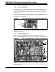
FIGURE 4-8: TYPICAL POWER METER CONNECTIONS
I
+
V
+
–
–
L
G
N
L
G
N
Reference Design
AC Mains
Series Ammeter Power Quality Meter
IV
+
–
L
G
N
L
G
N
SMPS AC/DC
Reference Design
AC Mains
Clamp-on Ammeter Power Quality Meter
SMPS AC/DC