
User`s guide


SMPS AC/DC Reference Design User’s Guide
DS70320B-page 70 © 2008 Microchip Technology Inc.
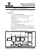
4.1.4 System Connections
4.1.4.1 INPUT CONNECTIONS
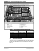
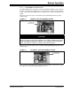
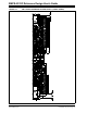
The AC input connector (J16) is shown in Figure 4-4. The SMPS AC/DC Reference
Design has a transparent lid (not shown in pictures) with a 12V fan mounted on it. There
are three holes provided in the lid to fasten the connection screws on the AC input
connector (J16).
Ensure that the power chord is not connected to the Variac or programmable AC source
(or AC Mains). Connect the AC cord with terminal lugs to the AC input connector in the
configuration shown in Figure 4-4.
FIGURE 4-4: SMPS AC/DC REFERENCE DESIGN INPUT CONNECTIONS
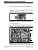
This is the minimum connection required to power up the SMPS AC/DC Reference
Design. However, other connections are recommended for detailed testing and
evaluation of the system.
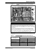
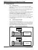
4.1.4.2 OUTPUT CONNECTIONS
Ensure that the SMPS AC/DC Reference Design is not powered. Connect DC
Electronic Loads (if available) to the 5V and 3.3V output terminals shown in Figure 4-5.
FIGURE 4-5: SMPS AC/DC REFERENCE DESIGN OUTPUT CONNECTIONS
A DC electronic load can be used to adjust the output power delivered by the SMPS
AC/DC Reference Design. If a DC electronic load is not available, a rheostat or
resistors with sufficient power ratings may also be used for loading the SMPS AC/DC
Reference Design.
Live
Earth
(No connection)
Neutral
+12V
GND
+3.3V
GND
+5V
GND