
User`s guide


System Operation
© 2008 Microchip Technology Inc. DS70320B-page 69
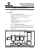
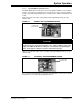
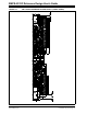
FIGURE 4-3: ISOLATION BOUNDARY ON SMPS AC/DC REFERENCE
DESIGN
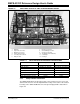
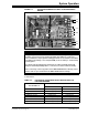
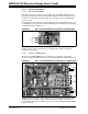
Table 4-2 lists the location where each functional block resides with respect to the
isolation barrier.
TABLE 4-2: LOCATION OF FUNCTIONAL BLOCK WITH RESPECT TO
ISOLATION BARRIER
Isolation Boundary
+12V
GND
+3.3V
GND
+5V
GND
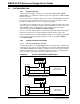
NOTICE
During testing and evaluation of the SMPS AC/DC Reference Design, no equipment
should be connected across the isolation boundary. This applies to oscilloscope
probes, multimeters, and programmers/debuggers. Under no circumstances should the
Live_GND (on the primary or “live” side) and GND (on the secondary or “isolated” side)
be tied together.
As a general rule, the primary (live) side and the secondary (isolated) side should
always be tested independently with no connections across the isolation boundary.
Before connecting oscilloscope probes to the SMPS AC/DC Reference Design, ensure
that the oscilloscope is isolated from the SMPS AC/DC Reference Design.
Functional Block
Live or Isolated Side?
Power Circuit Control Circuit
EMI Filter Primary (Live) N/A
Bridge Rectifier Primary (Live) N/A
PFC Boost Converter Primary (Live) Primary (Live)
Full-Bridge Converter Primary (Live) Primary (Live)
Synchronous Rectifier Secondary (Isolated) Primary (Live)
Multi-Phase Buck Converter Secondary (Isolated) Secondary (Isolated)
Single-Phase Buck Converter Secondary (Isolated) Secondary (Isolated)