
User`s guide


SMPS AC/DC Reference Design User’s Guide
DS70320B-page 68 © 2008 Microchip Technology Inc.
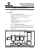
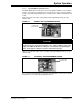
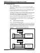
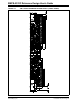
FIGURE 4-2: FUNCTIONAL BLOCKS OF SMPS AC/DC REFERENCE DESIGN
TABLE 4-1: INPUT AND OUTPUT ELECTRICAL SPECIFICATIONS
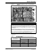
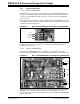
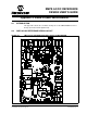
4.1.3 Safety Isolation Information
The SMPS AC/DC Reference Design provides safety isolation to protect users and
downstream electronics from the input AC Mains voltage. The location of the isolation
boundary on the SMPS AC/DC Reference Design is displayed with a dotted line in
Figure 4-3.
1
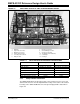
1. EMI Filter
2. Single-Phase Converter
3. Multi-Phase Converter
4. Primary Side Controller
5. Secondary Side Controller
6. Bridge Rectifier
2
3
4
5
6
7. PFC Boost Converter
8. ZVT Full-Bridge Converter
9. Synchronous Rectifier
10. 12V Output (Intermediate Bus)
11. 3.3V Output
12. 5V Output
7
8
9
10
11
12
Functional Block Input Output
EMI Filter 85-265V AC, 45-65 Hz 85-265V AC, 45-65 Hz
Bridge Rectifier 85-265V AC, 45-65 Hz 120-374V DC (unregulated)
PFC Boost Converter 120-374V DC (unregulated) 420V DC
Full-Bridge Converter 420V DC N/A
Synchronous Rectifier N/A 12V DC
Multi-Phase Buck Converter 12V DC 3.3V DC
Single-Phase Buck Converter 12V DC 5V DC