
User`s guide


SMPS AC/DC REFERENCE
DESIGN USER’S GUIDE
© 2008 Microchip Technology Inc. DS70320B-page 67
Chapter 4. System Operation
This chapter describes the system setup and operation of the SMPS AC/DC Reference
Design.
4.1 SYSTEM SETUP
4.1.1 Recommended Test Equipment
The following list of test equipment is recommended for complete evaluation of the
SMPS AC/DC Reference Design and/or development of software.
• Oscilloscope
• High Voltage Probe (100:1 attenuation ratio) or Differential Probe
• 10A AC Current Probe
• Power Quality Meter
• DC Electronic Load (350W or higher, and should have capability to load at least
two outputs simultaneously)
• 0V-265V Variac or Programmable AC Source (500W or higher)
• Two Digital Multimeters
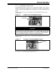
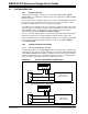
4.1.2 Functional Blocks of the System
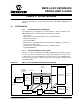
Figure 4-1 shows a block diagram of the SMPS AC/DC Reference Design. Table 4-1
describes the inputs and outputs of the system and also displays the location of the
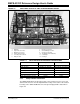
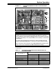
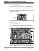
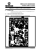
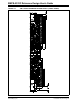
isolation barrier. To assist in identifying each functional block on the SMPS AC/DC
Reference Design, Figure 4-2 shows a top-view of the system with each block called
out with dotted lines.
FIGURE 4-1: SMPS AC/DC REFERENCE DESIGN BLOCK DIAGRAM
85-265 VAC
45-65 Hz
EMI Filter
and Bridge
Rectifier
PFC
Boost
Converter
ZVT
Full-Bridge
Converter
Synchronous
Rectifier
Optocoupler
3.3 VDC
69A
5 V
DC
23A
Isolation
Barrier
420 V
DC
Rectified
Sinusoidal
Voltage
Multi-Phase
Buck Converter
Single-Phase
Buck Converter
Phase-Shift ZVT Converter
dsPIC33FJ16GS504
dsPIC33FJ16GS504
12 VDC
30A