
User`s guide


Software Design
© 2008 Microchip Technology Inc. DS70320B-page 61
3.4 SECONDARY SIDE CONTROL SOFTWARE (DC_DC)
3.4.1 Single-Phase Buck Converter
3.4.1.1 SINGLE-PHASE BUCK CONVERTER CONTROL SCHEME
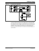
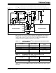
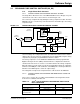
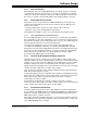
The Single-Phase Buck Converter on the SMPS AC/DC Reference Design uses peak
current mode control. The control scheme is shown in Figure 3-10.
The control loop is implemented by utilizing the analog comparator module. The Buck
MOSFET current is sensed using a current transformer and fed directly to the analog
comparator input.
FIGURE 3-10: SINGLE-PHASE BUCK CONVERTER CONTROL SCHEME
The measured output voltage is compared with the reference to produce the voltage
error. The voltage error compensator is then executed and a current reference value is
obtained. The current control loop is implemented on the dsPIC DSC using the analog
comparator by varying the programmable threshold in software.
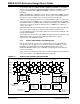
The analog comparators on the dsPIC33FJ16GS504 have built-in programmable
Digital-to-Analog Converters (DACs) that determine the comparator threshold. The
calculated current reference is used to set a new threshold for the analog comparator.
When the inductor current signal exceeds the programmed threshold, the comparator
terminates the PWM pulse. This termination of the PWM pulse effectively modifies the
ON time for the PWM signal to control the output voltage.
The Voltage Error Compensator is implemented as a PI function in the ADC ISR.
3.4.1.2 SINGLE-PHASE BUCK CONVERTER IMPLEMENTATION USING THE
dsPIC DSC
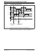
The resources used on the secondary side dsPIC DSC for the Single-Phase Buck
Converter are summarized in Table 3-4.
TABLE 3-4: dsPIC
®
DSC RESOURCE ALLOCATION FOR SINGLE-PHASE
BUCK CONVERTER
Σ
+
-
Voltage
Reference
V
OUT
Buck
Inductor
Voltage Feedback
PWM
Buck
Current
Sense
V
OUT
Sense
Voltage Error
Compensator
ADC
1001011011
S&H
Analog
Comparator
+
-
V
REF
Calculated
Current
Reference
Current-Limit
Shutdown
Description Type of Signal dsPIC
®
DSC Resource Used
Buck Current Analog Comparator Input CMP1A, AN0
Buck Voltage (V
OUT) Analog Input AN1
Single-Phase Synchronous
Buck Gate Drive
Drive Output PWM4H, PWM4L