
User`s guide


SMPS AC/DC Reference Design User’s Guide
DS70320B-page 58 © 2008 Microchip Technology Inc.
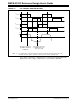
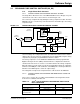
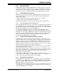
FIGURE 3-7: ZVT CURRENT SAMPLING INSTANTS
The voltage compensator is implemented as a Proportional-Integral-Derivative
(PID) function. The voltage compensator is executed in the ADC ISR.
Q
1PWM
Q
2PWM
Q
3PWM
Q
4PWM
I
p
I
pk
ADC Trigger generated
by PWM2 at beginning
of PWM cycle
ADC Trigger generated
by PWM1 at duty cycle
(1)
(1)
(1)
Note 1: The shaded regions represent the times when power is transferred from the primary side to the
secondary side. This region is sometimes referred to as the “effective” ZVT duty cycle.
minus phase shift