
User`s guide


Software Design
© 2008 Microchip Technology Inc. DS70320B-page 57
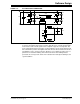
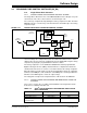
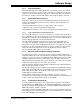
FIGURE 3-6: ZVT PHASE-SHIFT CONVERTER
Current sensing for the Phase-Shift ZVT Converter uses two dedicated analog inputs
to measure the primary transformer current in both directions. The two analog inputs
are tied to the same current signal, but are sampled at opposite current peaks. The
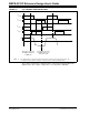
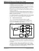
precise triggering instants are in Figure 3-7 along with the expected current waveform.
The current in the positive and negative directions must be measured and checked for
any imbalance. If the currents in the two directions are not balanced, it may cause a
phenomenon called “flux walking” in the ZVT transformer. Flux walking must be
prevented since it may lead to transformer saturation and subsequent damage to the
system hardware.
VIN
Q1
Q2
C
R
CR
IPRI
VPRI
Q4
Q3
L
R
VSEC
Q5
Q6
VOUT
CR
CR