
User`s guide


SMPS AC/DC Reference Design User’s Guide
DS70320B-page 54 © 2008 Microchip Technology Inc.
3.3 PRIMARY SIDE CONTROL SOFTWARE (PFC_ZVT)
The PFC Boost Converter and Phase-Shift ZVT Converter follow a similar control
scheme. However, there are significant differences in the operation of these two
converters. These differences will be explained in the description of the control
software for each converter.
3.3.1 PFC Boost Converter Control Software
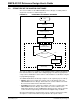
3.3.1.1 PFC CONTROL SCHEME
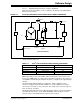
The control scheme implemented for the PFC Boost Converter is shown in Figure 3-3.
FIGURE 3-3: PFC CONTROL SCHEME
The PFC Boost Converter uses an outer voltage loop and inner current loop control
scheme. The output of the voltage error compensator is multiplied by a function of the
rectified AC mains voltage to generate a sinusoidal current reference.
An additional feed-forward term is introduced, |V
AC|MEAN, at the output of the voltage
error compensator to make the control loop immune to fluctuations in the AC input
voltage. This feed-forward term ensures that the PFC Boost Converter always delivers
the correct output power for the entire input voltage range.
The PFC voltage and current error compensators are both implemented as
Proportional-Integral (PI) systems with excess error compensation. The compensator
functions are math intensive routines and utilize the DSP engine of the dsPIC DSC.
The output of the PFC Current compensator modifies the PWM duty cycle to maintain
a constant output voltage and also a sinusoidal input current waveform.
Both the current and voltage compensators are executed in the ADC ISR. The current
control loop is executed at a much faster rate compared to the voltage control loop.
Σ
+
-
Voltage
Reference
VOUT
PFC
Choke
Voltage Feedback
PWM
Current
Feedback
PFC
Current
Sense
V
OUT
Sense
Voltage Error
Compensator
ADC
1001011011
1011001010
Current Error
Compensator
Σ
+
-
χ
Rectified
AC Mains
Voltage
Current
Reference
1
V
2
|VAC|MEAN
S&H
S&H
Calculated