
User`s guide


Software Design
© 2008 Microchip Technology Inc. DS70320B-page 53
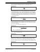
3.2.1 Initialization Routine
The initialization routines are called from the main program at the start of execution. All
peripherals including PWM, ADC, analog comparator, UART, I
2
C™ and Timers are
configured in this step. It is important that none of the peripherals are enabled before
the entire peripheral configuration is completed.
In addition to configuring the peripherals, all required interrupts and interrupt priorities
are configured in the initialization step. Memory allocation for control loop variables is
also done during the initialization stage.
3.2.2 Peripheral Enable Routine
After configuring all peripheral modules that are used in the project, we enable them in
the correct sequence. Since the PWM output directly affects the output of the system,
it is important to enable it after all other peripherals have been enabled.
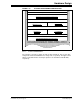
3.2.3 Soft-Start Routine
Each individual stage of the SMPS AC/DC Reference Design employs a controlled
soft-start routine. This routine ramps individual output stages to the desired output
voltage.
3.2.4 Fault Check Routine
The fault check routine is used to check for faults that have occurred in the system. If
a fault has occurred, the system has to be shut down. To do this, the fault loop is called
and used to disable all active modules, such as the ADC and PWM, and to visually
display the fault on the LEDs.
The PWM module on the dsPIC33FJ16GS504 has built-in fault inputs that ensure a
fast PWM shutdown in order to prevent damage to the system and downstream
electronics. After the PWM is shutdown, the program execution jumps to the fault loop.
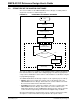
3.2.5 ADC Interrupt Service Routine
The ADC Interrupt Service Routine (ISR) is the heart of the control software. All control
loops are executed in the ISR. Since faster control loop execution is desired for the best
system performance, functions executed in this routine are written in Assembly
language. The ADC ISR has the highest priority of execution.
The ADC module is configured to generate interleaved interrupt requests in order to
execute multiple control loops within the same ISR.
The implementation of the control software for each stage of the SMPS AC/DC
Reference Design contains all the blocks described above. However, there are subtle
differences in the implementation for each stage.
Specific details for each stage of the design are covered in subsequent sections of this
user’s guide.