
User`s guide


Hardware Design
© 2008 Microchip Technology Inc. DS70320B-page 43
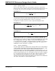
EQUATION 2-31:
Therefore, the total capacitor ripple current is 1.7 Arms. Another important design
consideration for the bulk capacitors is the transient load requirements, so low
ESR/ESL parts are required to meet the specification (see Reference 12 in Appendix
C. “References”). Two Rubycon 10ZL1500M10X23 1500 μF, 10V electrolytic
capacitors, plus four 10 μF, 16V multi-layer ceramics in parallel were selected. The
electrolytic capacitors are each rated to 2.15 Arms at 105ºC, which can easily handle
the ripple current on their own.
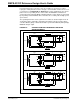
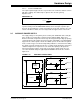
2.4 THREE-PHASE SYNCHRONOUS BUCK CONVERTER
Multiple synchronous Buck converters can be connected in parallel to increase the
power handling of a step-down voltage stage. Performance improvements and a
reduction in output capacitor size can be achieved by phase-shifting the PWM
modulation in each stage. In this reference design, a Three-Phase Synchronous Buck
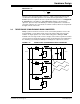
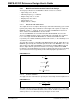
converter has been designed. The power circuit is shown in Figure 2-12 and illustrates
the switching cycle 120 degree PWM phase-shifting in the output choke currents.
FIGURE 2-12: THREE-PHASE SYNCHRONOUS BUCK CONVERTER
12
cap
i
i
Δ
=
%
VBUS
VOUT