
User`s guide


SMPS AC/DC Reference Design User’s Guide
DS70320B-page 38 © 2008 Microchip Technology Inc.
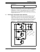
In push-pull type power converters, there are a number of synchronous rectifier
topologies. In this particular reference design, a current-doubler form has been used
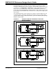
(see Reference 10 in Appendix C. “References”). Figure 2-9 illustrates the current
paths for the four operating modes of the rectifier. The MOSFET commutation is
synchronized to the ZVT Full-Bridge switching and gate control signals are generated
by the primary-side dsPIC DSC device and fed to the secondary-side via high-speed
opto-isolators.
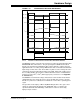
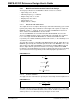
The operating waveforms for the synchronous rectifier are shown in Figure 2-10. As
shown in the figure, switch Q6 is gated when the primary current is positive, which
coincides with the gating of switch Q2, and Q5 is synchronized with the primary bridge
MOSFET Q4 gate signal.
FIGURE 2-9: CURRENT-DOUBLER SYNCHRONOUS RECTIFIER
OPERATING MODES
Note: Dotted lines with arrows indicate current polarity.
V
SEC
I
SEC
Q
5
Q
6
I
1
I
OUT
V
OUT
I
2
V
SEC
I
SEC
Q
5
Q
6
I
1
I
OUT
V
OUT
I
2
V
SEC
I
SEC
Q
5
Q
6
I
1
I
OUT
V
OUT
I
2