
User`s guide


Hardware Design
© 2008 Microchip Technology Inc. DS70320B-page 37
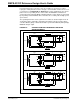
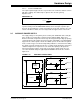
FIGURE 2-8: ZVT FULL-BRIDGE TRANSFORMER WINDING
CONSTRUCTION
The last check is to assess whether an additional inductor is needed for ZVT operation.
The leakage inductance (see Reference 8 in Appendix C. “References”) for a
standard construction transformer is given by Equation 2-22.
EQUATION 2-22:
The ideal computed leakage inductance is 32 µH, which meets the criteria of
Equation 2-9 with the MOSFET output capacitance without requiring an additional
resonant inductor. Provision has been made on the reference design PCB for an
external inductor and parallel capacitors across the MOSFETs if the ZVT operation
needs tuning.
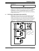
2.2.2 Synchronous Rectifier Design
Synchronous rectification is the technique used for reducing the power loss in the
output stage of switched mode power supplies (see Reference 9 in Appendix
C. “References”). The conventional diode is replaced by a MOSFET and is controlled
so that current will flow into the third quadrant in the source-to-drain direction when the
equivalent R
DS(ON) voltage drop is lower than the intrinsic diode voltage drop. This
means that with very low R
DS(ON) MOSFETs, the power supply efficiency can be
significantly increased. This is especially true in low output voltage power supplies.
3 mm
margin
3 mm
margin
3 mm
margin
3 mm
margin
64 turns of 8 x 0.2 mm Litz wire
3 layers 0.05 mm Melinex
5 turns of 0.1 mm x 13 mm foil
3 layers 0.05 mm Melinex
42
410
3
mp p s
L
w
lN h h
Lc
b
π
−
×+
⎛⎞
=+
⎜⎟
⎝⎠
µH
where c is the space between the primary and secondary.
All dimensions are in mm.