
User`s guide

SMPS AC/DC Reference Design User’s Guide
DS70320B-page 36 © 2008 Microchip Technology Inc.
There is no requirement to reduce leakage inductance in the transformer design so the
primary winding can be a single winding block. This may also reduce the inter-winding
capacitance between primary and secondary and have an impact on EMC. For the low
current primary with the large number of turns, round conductors are preferred.
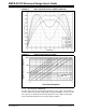
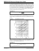
Equation 2-20 can be used to identify the ideal wire diameter at the operating
frequency, which takes into account skin and proximity effects, and was derived
through experimental work by Dowell in the 1960s (see Reference 7 in Appendix
C. “References”).
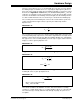
EQUATION 2-20:
The resistance factor for round conductors can then be computed from Equation 2-21.
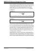
EQUATION 2-21:
The best fill factor is achieved by using seven-stranded Litz wire, so this is a starting
point. Also, assume four layers as an initial starting point with 16 turns per layer.
Therefore, the ideal optimum wire diameter is 0.2 mm (32 AWG), giving a resistance
factor of 1.5. A commercially available Litz wire has eight strands of 0.2 mm with an OD
of 0.75 mm. The DC resistance per meter for single 0.2 mm strand at 100ºC is 0.7074
Ω/m, so the resistance for one mean turn of eight strands is 4.7 mΩ. Therefore, the total
adjusted AC resistance of the primary winding is 0.45Ω. The primary current is 1.3
Arms for the estimated secondary current and selected transformer turns ratio, which
leads to a primary winding loss of 0.8W. Therefore, the total transformer losses are
estimated to be 4.2W in the ETD29 transformer, and will limit the total temperature rise
to less than 80ºC with forced air-cooling.
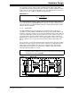
The primary Litz wire has a total OD of around 0.7 mm, so the four-layer primary
winding height is about 3 mm. The secondary five-layer foil winding height, including
inter-turn insulation, will be around 0.75 mm height, and this design will easily fit in the
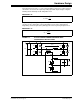
available 4.85 mm maximum winding window height. The final winding construction is
shown in Figure 2-8. The primary winding start and finish are terminated to bobbin pins,
while the secondary winding has flying leads which are soldered directly into the PCB.
1
3
17.1
1.01
w
id
sw
b
d
SNf
⎛⎞
=
⎜⎟
⎝⎠
where S is the number of strands and N is number of turns in the winding portion.
6
1
1
2
R
id
d
F
d
⎛⎞
=+
⎜⎟
⎝⎠