
User`s guide

Hardware Design
© 2008 Microchip Technology Inc. DS70320B-page 31
The transformer turns ratio, n, for the current doubling synchronous rectifier topology
can then be selected for the required operating input and output voltages using the
following ideal relationship shown in Equation 2-12.
EQUATION 2-12:
The previous equations governing the ZVT operation and resonant circuit component
selection are also dependent on the peak primary current. If the output inductor
magnetizing current is ignored, the primary peak current is given by Equation 2-13.
EQUATION 2-13:
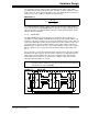
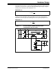
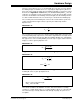
FIGURE 2-5: ZVT FULL-BRIDGE POWER CONVERTER WITH
SYNCHRONOUS RECTIFICATION
max
2
in
o
V
nD
V
=
2
oin
pri
o
I
V
I
nV
=
VIN
Q1
Q2
C
R
CR
IPRI
VPRI
Q4
Q3
L
R
VSEC
Q5
Q6
VOUT
CR
CR