
User`s guide

Hardware Design
© 2008 Microchip Technology Inc. DS70320B-page 29
The capacitance must be high enough to maintain the PFC output voltage within
acceptable bounds under normal peak power operating conditions and when a mains
brown-out occurs. The required hold-up time, t
hold
, at the minimum mains frequency is
22 ms, therefore the conditions of Equation 2-8 must be met.
EQUATION 2-8:
For a minimum DC link voltage of 300V, a 330 μF is required. The actual capacitor
selected is a Panasonic EET-ED2W331EA 35 x 40 mm electrolytic capacitor rated to
450 V
DC and 105ºC. The ESR at 20 kHz is 0.181Ω, and the maximum ripple current
rating at 105ºC is 2.64 Arms.
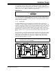
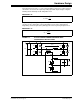
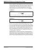
2.1.1.5 EMI FILTER
The SMPS AC/DC Reference Design has been designed to meet international
standards for conducted EMC. The EMI filter between the mains input terminals and
the PFC is a two-stage design because of the high switching frequency of the different
stages in the SMPS. The circuit is shown in Figure 2-4. The two common-mode chokes
are rated to 6 Arms, and the 2.2 mH inductance forms a filter with the capacitors to
Earth Ground for common-mode noise. The leakage inductance of the chokes together
with the capacitors across the live and neutral terminals, filter the differential-mode
noise.
The six capacitors connected to Earth Ground are 2.2 nF Y2-class capacitors meeting
the CATII overvoltage category. The two X2-class capacitors are 220 nF. A transient
spike voltage protection MOV is also fitted across the mains input, and a 470 kΩ
discharging resistor is fitted across the input to the SMPS to ensure that the filter
capacitors discharge within one second.
FIGURE 2-4: EMI FILTER
()
22
(min)
2
hold o
dc dc
tP
C
VV
>
−
Note: The EMI/EMC filter value has been chosen based on switching frequencies
and expected noise levels in the system. This value may be changed based
on the final test results of EMI/EMC.
Mains
L
N
E
L
N
E