
User`s guide

Hardware Design
© 2008 Microchip Technology Inc. DS70320B-page 27
In this design, the diode must be rated for 1.2A, so a STMicroelectronics STTH5R06D
600V, 5A TO-220 ultra-fast high-voltage rectifier has been selected. The typical forward
voltage drop at high junction temperature is 1.4V, which means that the device will run
cool since the dissipation is only 1.7 Watts. There will be additional switching losses
due to the high switching frequency and diode recovery characteristics. For a lower
cost solution, a smaller axial diode may be used. Alternatively, if switching losses are
an issue, then the recently introduced SiC Schottky diode would be an attractive option.
2.1.1.3 PFC CHOKE
The target THD of the input current is 5%, which means the non-fundamental (50 Hz
nominal) rms current component must be only 1% of input rms current. This component
is the high-frequency ripple current in the Boost inductor, and is dependent on the
inductance. If it is assumed that, on average, the duty cycle is 0.5, the ripple current
rms of a triangular waveform is given by Equation 2-5.
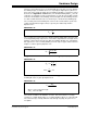
EQUATION 2-5:
Therefore, for a 5.3 Arms input current, we can only allow a maximum of 0.2A
peak-to-peak, which will entail a large inductor size. However, the high frequency
capacitor placed across the output terminals of the bridge rectifier will shunt-off most of
the high frequency current so that a larger component of ripple can be tolerated in a
smaller inductor. Note that too large a capacitance will cause distortion in the current
waveform, so a design compromise must be reached. The inductor current
peak-to-peak ripple in a PFC Boost converter varies over the whole mains cycle and
depends on the input voltage, as shown in Equation 2-6.
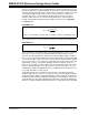
EQUATION 2-6:
However, the absolute maximum value is independent of input voltage and is
calculated from Equation 2-7.
EQUATION 2-7:
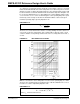
In this design, the ripple current is chosen to be 25% of the minimum voltage peak
mains current; therefore, inductance of about 400 μH is required. The Boost choke
uses a Kool Mu 77548 core, which has an outside diameter of 33 mm. The A
L value for
this core is 127. A single layer of 58 turns of 0.9 mm (19 AWG) enameled copper fits
on the core giving an unsaturated inductance of 427 μH. From the Magnetics Inc.
published wire-core tables, this results in a predicted winding resistance of 77 mΩ at
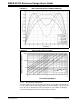
100ºC. The variation of ripple current for a selection of input voltages is shown in
Figure 2-2 and Figure 2-3.
The core loss can be roughly estimated from the mean flux density over a complete
mains cycle. The worst case condition occurs at roughly 180 Vrms, where the mean
flux density is 180 mT.
2
12
pk pk
rm s
I
I
−
=
ac
ripple
s
w
D
V
i
L
f
=
)
ˆ
4
dc
ripple
s
w
V
i
L
f
=