
User`s guide


SMPS AC/DC Reference Design User’s Guide
DS70320B-page 24 © 2008 Microchip Technology Inc.
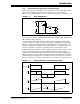
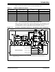
Table 1-4 shows the dsPIC DSC resources used by Multi-Phase as well as
Single-Phase Synchronous Buck converters.
TABLE 1-4: RESOURCES REQUIRED FOR SECONDARY SIDE SYNCHRONOUS BUCK
CONVERTERS
Description/Signal Name Type of Signal
dsPIC
®
DSC Resources
Used
Expected Signal Level
5V Buck Current Analog AN0, CMP1A 1.25V (maximum)
5V Buck Output Analog AN1 2.7V (nominal)
3.3V Buck Current 1 Analog AN2, CMP2A 1V (maximum)
3.3V Buck Current 2 Analog AN4, CMP3A 1V (maximum)
3.3V Buck Current 3 Analog AN6, CMP4A 1V (maximum)
3.3V Buck Output Analog AN3 1.65V (nominal)
5V Buck Gate Drive Single-Phase Synchronous
Buck Drive
PWM4H, PWM4L —
3.3V Buck Gate Drive Multi-Phase Synchronous
Buck Drive
PWM1H, PWM1L,
PWM2H, PWM2L,
PWM3H, PWM3L,
—
12V Bus Sense Analog AN5 2.79V
12V Digital Feedback Digital UART1 Transmit —
RS232_RX Digital UART1 Receive —
Temperature Sense Analog AN8 1.4V
MCLR
Digital MCLR —
PGC Digital PGC —
PGD Digital PGD —
Fault_Reset Digital RC6 —