
User`s guide


Introduction
© 2008 Microchip Technology Inc. DS70320B-page 23
Table 1-3 shows the common resources used on the Primary side.
TABLE 1-3: PRIMARY COMMON RESOURCES
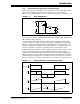
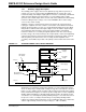
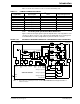
1.4.3 Secondary Side Synchronous Buck Converters
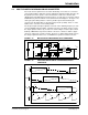
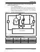
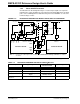
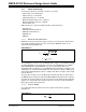
Figure 1-20 shows the input signals required to implement the control algorithms for the
synchronous Buck converters. The output from the dsPIC DSC device is firing pulses
to the Multi-Phase as well as Single-Phase Synchronous Buck converters.
FIGURE 1-20: RESOURCES REQUIRED FOR DIGITAL SYNCHRONOUS BUCK CONVERTERS
Signal Name Type of Signal
dsPIC
®
DSC Resources
Used
Expected Signal Level
Live_MCLR Digital MCLR
—
Live_PGC Digital PGC —
Live_PGD Digital PGD —
Live_Fault Digital RC6 —
Live_RS232_TX Digital UART1 Transmit —
Live_RS232_RX Digital UART1 Receive —
Live_Temp_Sense Analog AN10 1.4V
k
6
Analog
Comp.
UART
TX
k
10
k
7
k
9
k
8
k
11
k
5
PWM
PWM
ADC
Channel
Analog Comparator
Analog Comparator
ADC Channel
Analog Comparator
ADC
Channel
PWM
PWM
PWM
PWM
PWM
PWM
3.3V Output
5V Output
I
5V
12V Input
FET
Driver
FET
Driver
FET
Driver
FET
Driver
I
3.3V_3
I
3.3V_2
I
3.3V_1
dsPIC33FJ16GS504
Note 1: K
5
through K
11
are feedback gain circuits. See A.3 “SMPS AC/DC Reference Design Schematics” for
detailed schematics.
(1)
(1)
(1)
(1)
(1)
(1)
(1)