
User`s guide


Introduction
© 2008 Microchip Technology Inc. DS70320B-page 19
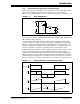
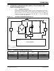
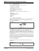
1.3 MULTI-PHASE SYNCHRONOUS BUCK CONVERTER
If the load current requirement is more than 35-40 amps, more than one converter is
connected in parallel to deliver the load. To optimize the input and output capacitors, all
the parallel converters operate on the same time base and each converter starts
switching after a fixed time/phase from the previous one. This type of converter is called
a Multi-Phase Synchronous Buck converter, which is shown in Figure 1-15. Figure 1-16
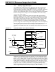
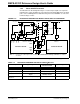
shows gate pulse timing relation of each leg and the input current drawn by the
converter. The fixed time/phase is given by Time period/n (or 360/n), where “n” is the
number of the converters connected in parallel.
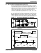
The design of input and output capacitors is based on the switching frequency of each
converter multiplied by the number of parallel converters. The ripple current seen by
the output capacitor reduces by “n” times. As shown in Figure 1-16, the input current
drawn by a Multi-Phase Synchronous Buck converter is continuous, with less ripple
current as compared to a single converter. Therefore, a smaller input capacitor meets
the design requirement in the case of a Multi-Phase Synchronous Buck converter.
FIGURE 1-15: MULTI-PHASE SYNCHRONOUS BUCK CONVERTER
FIGURE 1-16: SWITCHING WAVEFORM OF SYNCHRONOUS BUCK
CONVERTER
+
-
Q
1
IQ
1
Q
2
Q
3
IQ
3
Q
4
Q
5
Q
6
I
L3
L
3
L
2
L
1
IQ
5
I
L2
I
L1
V
IN
V
OUT
C
O
Q
1PWM
I
IN
IQ
5
+IQ
1
IQ
1
IQ
3
IQ
5
Q
3PWM
Q
5PWM
IQ
1
+IQ
3
IQ
3
+IQ
5
IQ
5
+IQ
1
t
t
t
t
I
L1
I
L2
I
L3