
User`s guide

Introduction
© 2008 Microchip Technology Inc. DS70320B-page 15
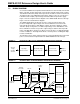
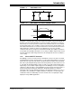
Power is transferred to the secondary only when the diagonal switches are ON. If the
top or bottom switches of both legs are ON simultaneously, zero voltage is applied
across the transformer primary. Therefore, no power is transferred to the secondary
during this period. When the appropriate diagonal switch is turned OFF, primary current
flows through the output capacitor of the respective MOSFETs causing switch drain
voltage to move toward to the opposite input voltage rail. This creates zero voltage
across the MOSFET to be turned ON next, which creates zero voltage switching when
it turns ON. This is possible when enough circulating current is provided by the
inductive storage energy to charge and discharge the output capacitor of the respective
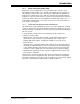
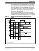
MOSFETs. Figure 1-12 shows the gate pulse required, and the voltage and current
waveform across the switch and transformer.
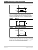
The operation of the Phase-Shift ZVT can be divided into different time intervals.
Assuming that the transformer was delivering the power to the load, the current flowing
through primary is I
PK, and the diagonal switch Q1,Q3 was ON, at t = t0, the switch Q3
is turned OFF as shown in Figure 1-12.
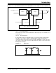
FIGURE 1-12: REQUIRED GATE PULSES AND VOLTAGE AND CURRENT ACROSS
PRIMARY
Q
1PWM
Q
2PWM
Q
3PWM
Q
4PWM
Vprimary
I
p
t0 t1 t2 t3 t4
I
PK
(A) = Gate pulse for all switches for Phase-Shift ZVT converter
(B) = Voltage across primary
(C) = Current across primary
(A)
(B)
(C)