
User`s guide

SMPS AC/DC Reference Design User’s Guide
DS70320B-page 10 © 2008 Microchip Technology Inc.
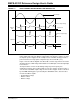
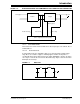
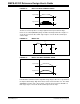
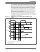
FIGURE 1-3: INPUT CURRENT WAVEFORM WITH AND WITHOUT PFC
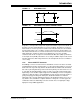
These waveforms illustrate that PFC can improve the input current drawn from the
mains supply and reduce the DC bus voltage ripple. The objective of PFC is to make
the input to a power supply look like a simple resistor. The PFC circuitry provides a
power factor that is nearly equal to unity with very low current THD (< 5%).
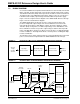
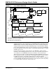
Figure 1-4 shows a block diagram of the AC-to-DC converter stage, which converts the
AC input voltage to a DC voltage and maintains sinusoidal input current at a high input
Power Factor.
The input rectifier converts the alternating voltage at power frequency into
unidirectional voltage. This rectified voltage is fed to the chopper circuit to produce a
smooth and constant DC output voltage to the load. The chopper circuit is controlled
by the PWM switching pulses generated by the dsPIC DSC device, based on three
measured feedback signals:
• Rectified input voltage
• DC bus current
• DC bus voltage
Input Voltage
DC Bus Output Voltage
Input Current
DC Bus Output Voltage
Input Current
Without
PFC
With PFC
0
0