
User`s guide

Introduction
© 2008 Microchip Technology Inc. DS70320B-page 9
1.2.1 Power Factor Correction (PFC)
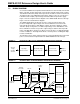
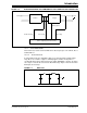
Most power conversion applications consist of an AC-to-DC conversion stage
immediately following the AC source. The DC output obtained after rectification is
subsequently used for further stages. Current pulses with high peak amplitude are
drawn from a rectified voltage source with sine wave input and capacitive filtering.
Regardless of the load connected to the system, the current drawn is discontinuous
and of short duration. Because many applications demand a DC voltage source, a
rectifier with a capacitive filter is necessary. However, this results in discontinuous,
short duration current spikes.
1.2.1.1 OVERVIEW AND BACKGROUND INFORMATION
Two factors that provide a quantitative measure of the power quality in an electrical
system are Power Factor (PF) and Total Harmonic Distortion (THD). The amount of
useful power being consumed by an electrical system is predominantly decided by the
PF of the system.
To understand PF, it is important to know that power has two components:
• Working (or Active Power)
Working Power is the power that is actually consumed and registered on the
electric meter at the consumer's location. Working power is expressed in
kilowatts (kW), which register as kilowatt hour (kWh) on an electric meter.
• Reactive Power
Reactive Power is required to maintain and sustain the electromagnetic field asso-
ciated with the industrial inductive loads such as induction motors driving pumps
or fans, welding machines and many more. Reactive Power is measured in kilo-
volt ampere reactive (kVAR) units. The total required power capacity, including
Working Power and Reactive Power, is known as Apparent Power, expressed in
kilovolt ampere (kVA) units.
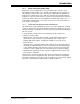
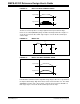
Power Factor is a parameter that gives the amount of working power used by any
system in terms of the total apparent power. Power Factor becomes an important
measurable quantity because it often results in significant economic savings. Typical
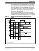
waveforms of current with and without PFC are shown in Figure 1-3.