
User`s guide


Test Results
© 2008 Microchip Technology Inc. DS70320B-page 101
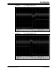
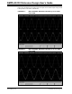
FIGURE B-12: 12V OUTPUT VOLTAGE RIPPLE
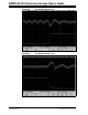
B.4 INPUT CURRENT
The SMPS AC/DC Reference Design implements Power Factor Correction (PFC)
where the current is in phase with the input voltage.
B.4.1 Test Procedure:
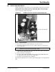
1. Ensure that the system is off and that all probes are disconnected.
2. Connect a differential probe across the input terminal (J16). Connect across the
“neutral” and “live” terminals.
3. Connect the current probe around the live or neutral power cable making sure of
the direction of current flow.
4. Set the current probe for 100 mV per Amp and set the oscilloscope channel to a
1:1 ratio.
5. Connect load cables to the 12V output (J1).
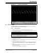
6. Verify your connections and turn on the system. You should be able to observe
sinusoidal input voltage and current. If not, connect the current probe to the other
input.
7. Apply a load to the output and verify that the current and the voltage are still
sinusoidal and in phase.
8. Turn off the system and disconnect all probes.
WARNING
Do not connect a standard probe across the AC terminal. A differential probe must be
used. Failure to heed this warning may result in bodily harm and damage to the
oscilloscope and/or SMPS AC/DC Reference Design.