
User`s guide


Test Results
© 2008 Microchip Technology Inc. DS70320B-page 99
B.3 OUTPUT VOLTAGE RIPPLE
Output voltage ripple is measured across the output capacitors with the shortest probe
ground possible. For production tests, the output voltage ripple is measured at the
terminal blocks. Refer to Figure B-9 for the oscilloscope probe connection location
used to measure the output voltage ripple.
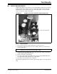
FIGURE B-9: EXAMPLE OF OSCILLOSCOPE PROBE CONNECTION
B.3.1 Test Procedure
1. Ensure that the system is OFF and all probes are disconnected.
2. Connect the oscilloscope probe across the output capacitor to be measured as
shown in Figure B-9.
3. Set up the oscilloscope with a time scale of 2 µs and set the oscilloscope channel
to AC coupling and 50 mV per division.
4. Measure the peak-to-peak voltage.
5. To test the output voltage ripple with a load, connect a programmable DC load to
the output terminal and re-measure the voltage ripple.
6. Turn off the system and disconnect all probes.
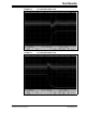
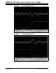
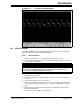
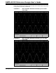
Figure B-10 through Figure B-12 show the output voltage ripple of each stage without
load.
Probe connection point
Note: Oscilloscope probes should have the shortest ground wire possible to
eliminate noise when measuring the ripple voltage.