SMPS AC/DC Reference Design User’s Guide © 2008 Microchip Technology Inc.
Note the following details of the code protection feature on Microchip devices: • Microchip products meet the specification contained in their particular Microchip Data Sheet. • Microchip believes that its family of products is one of the most secure families of its kind on the market today, when used in the intended manner and under normal conditions. • There are dishonest and possibly illegal methods used to breach the code protection feature.
SMPS AC/DC REFERENCE DESIGN USER’S GUIDE Table of Contents Preface ........................................................................................................................... 1 Chapter 1. Introduction 1.1 System Specifications .................................................................................... 7 1.2 Block Diagram ................................................................................................ 8 1.3 Multi-Phase Synchronous Buck Converter ......................
SMPS AC/DC Reference Design User’s Guide Appendix B. Test Results B.1 Soft-Start and Overshoot ............................................................................. 93 B.2 Dynamic Load Response ............................................................................. 95 B.3 Output Voltage Ripple .................................................................................. 99 B.4 Input Current ..............................................................................................
SMPS AC/DC REFERENCE DESIGN USER’S GUIDE Preface NOTICE TO CUSTOMERS All documentation becomes dated, and this manual is no exception. Microchip tools and documentation are constantly evolving to meet customer needs, so some actual dialogs and/or tool descriptions may differ from those in this document. Please refer to our web site (www.microchip.com) to obtain the latest documentation available. Documents are identified with a “DS” number.
SMPS AC/DC Reference Design User’s Guide • Appendix A. “Board Layouts and Schematics” – This appendix provides detailed technical drawings and schematic diagrams of the SMPS AC/DC Reference Design. • Appendix B. “Test Results” – This appendix provides information on obtaining the source code referenced in this document. • Appendix C. “References” – This appendix provides detailed information on all external references used throughout this document. DS70320B-page 2 © 2008 Microchip Technology Inc.
Preface CONVENTIONS USED IN THIS GUIDE This manual uses the following documentation conventions: DOCUMENTATION CONVENTIONS Description Arial font: Italic characters Initial caps Quotes Underlined, italic text with right angle bracket Bold characters N‘Rnnnn Text in angle brackets < > Courier New font: Plain Courier New Represents Referenced books Emphasized text A window A dialog A menu selection A field name in a window or dialog A menu path MPLAB® IDE User’s Guide ...is the only compiler...
SMPS AC/DC Reference Design User’s Guide WARRANTY REGISTRATION Please complete the enclosed Warranty Registration Card and mail it promptly. Sending in the Warranty Registration Card entitles users to receive new product updates. Interim software releases are available at the Microchip web site. RECOMMENDED READING This user's guide describes how to use SMPS AC/DC Reference Design. Other useful documents are listed below.
Preface DEVELOPMENT SYSTEMS CUSTOMER CHANGE NOTIFICATION SERVICE Microchip’s customer notification service helps keep customers current on Microchip products. Subscribers will receive e-mail notification whenever there are changes, updates, revisions or errata related to a specified product family or development tool of interest. To register, access the Microchip web site at www.microchip.com, click on Customer Change Notification and follow the registration instructions.
SMPS AC/DC Reference Design User’s Guide NOTES: DS70320B-page 6 © 2008 Microchip Technology Inc.
SMPS AC/DC REFERENCE DESIGN USER’S GUIDE Chapter 1. Introduction This chapter provides an introduction to the SMPS AC/DC Reference Design and includes the following major topics: • • • • 1.
SMPS AC/DC Reference Design User’s Guide 1.2 BLOCK DIAGRAM A conventional SMPS must implement PFC if it draws more than 75 watts from the AC Mains. The PFC circuitry draws input current in phase with the input voltage, and the Total Harmonic Distortion (THD) of the input current should be less than 5% at full load. The PFC provides a fixed DC high-output voltage, which needs to be converted to a lower Direct Current (DC) output voltage and isolated with an input mains supply.
Introduction 1.2.1 Power Factor Correction (PFC) Most power conversion applications consist of an AC-to-DC conversion stage immediately following the AC source. The DC output obtained after rectification is subsequently used for further stages. Current pulses with high peak amplitude are drawn from a rectified voltage source with sine wave input and capacitive filtering. Regardless of the load connected to the system, the current drawn is discontinuous and of short duration.
SMPS AC/DC Reference Design User’s Guide FIGURE 1-3: INPUT CURRENT WAVEFORM WITH AND WITHOUT PFC Input Voltage 0 DC Bus Output Voltage Without PFC Input Current 0 DC Bus Output Voltage With PFC Input Current These waveforms illustrate that PFC can improve the input current drawn from the mains supply and reduce the DC bus voltage ripple. The objective of PFC is to make the input to a power supply look like a simple resistor.
Introduction FIGURE 1-4: BLOCK DIAGRAM OF THE COMPONENTS FOR POWER FACTOR CORRECTION Load AC Input Rectifier Chopper Switching pulses Rectified Voltage Bus Current DC Voltage dsPIC® Digital Signal Controller (DSC) 1.2.1.2 PFC TOPOLOGIES The Power Factor can be achieved with various basic topologies such as Buck, Boost and Buck/Boost. 1.2.1.2.1 Buck PFC Circuit In a Buck PFC circuit, the output DC voltage is less than the input rectified voltage.
SMPS AC/DC Reference Design User’s Guide FIGURE 1-6: BUCK PFC INPUT CURRENT SHAPE Input Voltage t Input Current t 1.2.1.2.2 Boost PFC Circuit The Boost converter produces a voltage higher than the input rectified voltage; therefore, the switch (MOSFET) rating should be rated higher than VOUT. Figure 1-7 shows the circuit for the Boost PFC stage. Figure 1-8 shows the Boost PFC input current shape.
Introduction FIGURE 1-9: BUCK/BOOST PFC D L FIGURE 1-10: Co + BUCK/BOOST PFC INPUT CURRENT SHAPE Input Voltage t Input Current t Regardless of the input line voltage and output load variations, input current drawn by the Buck converter and the Buck/Boost converter is always discontinuous. However, when the Boost converter operates in Continuous Conduction mode, the current drawn from the input voltage source is always continuous and smooth as shown in Figure 1-8.
SMPS AC/DC Reference Design User’s Guide FIGURE 1-11: FULL-BRIDGE CONVERTER Q1 + Q4 COSS1 COSS4 D3 + L VL LLKG (A) - VOUT CO VIN - Q3 COSS2 COSS3 D4 Q2 TS Q1PWM Q3PWM TON TOFF (B) Q4PWM Q2PWM (C) VIN VIN (D) (A) = Full-Bridge/Half-Bridge Phase-Shift ZVT converter (B) = PWM gate pulse waveform for Full-Bridge switches (C) = Voltage across the transformer primary (D) = Output inductor and rectifier diode current In the Full-Bridge converter, four switches are used, thereby increasing
Introduction Power is transferred to the secondary only when the diagonal switches are ON. If the top or bottom switches of both legs are ON simultaneously, zero voltage is applied across the transformer primary. Therefore, no power is transferred to the secondary during this period. When the appropriate diagonal switch is turned OFF, primary current flows through the output capacitor of the respective MOSFETs causing switch drain voltage to move toward to the opposite input voltage rail.
SMPS AC/DC Reference Design User’s Guide 1.2.2.1 TIME INTERVALS • Interval1: t0 < t < t1 Switch Q3 is turned OFF, beginning the resonant transition of the right leg. Primary current is maintained constant by the resonant inductor LLK. The primary current charges the output capacitor of switch Q3 (COSS3) to the input voltage VIN, which results in the output capacitance of Q4 (COSS4) being discharged to zero potential.
Introduction 1.2.3 Buck Converter Description and Background A Buck converter, as its name implies, can only produce lower average output voltage than the input voltage. The basic schematic of a Buck converter is shown in Figure 1-13. The switching waveforms for a Buck converter are shown in Figure 1-14. FIGURE 1-13: BUCK CONVERTER IIN Q1 L VIN IOUT + IL - D1 VOUT In a Buck converter, a switch (Q1) is placed in series with the input voltage source VIN.
SMPS AC/DC Reference Design User’s Guide The inductor current is continuous and never reaches zero during one switching period (TS); therefore, this mode of operation is known as Continuous Conduction mode. In Continuous Conduction mode, the relation between the output and input voltage is given by Equation 1-1. The duty cycle is given by Equation 1-2.
Introduction 1.3 MULTI-PHASE SYNCHRONOUS BUCK CONVERTER If the load current requirement is more than 35-40 amps, more than one converter is connected in parallel to deliver the load. To optimize the input and output capacitors, all the parallel converters operate on the same time base and each converter starts switching after a fixed time/phase from the previous one. This type of converter is called a Multi-Phase Synchronous Buck converter, which is shown in Figure 1-15.
SMPS AC/DC Reference Design User’s Guide 1.3.1 Auxiliary Supply Description The auxiliary power supply is based on the flyback topology, where it generates a voltage source for the control circuitry and MOSFET drivers on both sides of the isolation boundary. The multiple output flyback converter is controlled by a TNY277G switch; the block diagram is shown in Figure 1-17.
Introduction 1.4 LISTING OF I/O SIGNALS FOR EACH BLOCK, TYPE OF SIGNAL AND EXPECTED SIGNAL LEVELS 1.4.1 PFC Boost Converter As indicated in the block diagram in Figure 1-18, three input signals are required to implement the control algorithm. The only output from the dsPIC DSC device is firing pulses to the Boost converter switch to control the nominal voltage on the DC bus in addition to presenting a resistive load to the AC line. Table 1-1 shows the dsPIC DSC resources used by the PFC application.
SMPS AC/DC Reference Design User’s Guide 1.4.2 Phase-Shift ZVT Converter As indicated in the block diagram in Figure 1-19, three input signals are required to implement the control algorithm. The only outputs from the dsPIC DSC device are firing pulses to the Full-Bridge Phase-Shift ZVT and synchronous MOSFETs to control the nominal voltage on VOUT.
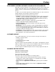
Introduction Table 1-3 shows the common resources used on the Primary side. TABLE 1-3: PRIMARY COMMON RESOURCES Type of Signal dsPIC® DSC Resources Used Expected Signal Level Live_MCLR Digital MCLR — Live_PGC Digital PGC — Live_PGD Digital PGD — Live_Fault Digital RC6 — Live_RS232_TX Digital UART1 Transmit — Live_RS232_RX Digital UART1 Receive — Live_Temp_Sense Analog AN10 1.4V Signal Name 1.4.
SMPS AC/DC Reference Design User’s Guide Table 1-4 shows the dsPIC DSC resources used by Multi-Phase as well as Single-Phase Synchronous Buck converters. TABLE 1-4: RESOURCES REQUIRED FOR SECONDARY SIDE SYNCHRONOUS BUCK CONVERTERS Type of Signal dsPIC® DSC Resources Used Expected Signal Level 5V Buck Current Analog AN0, CMP1A 1.25V (maximum) 5V Buck Output Analog AN1 2.7V (nominal) 3.3V Buck Current 1 Analog AN2, CMP2A 1V (maximum) 3.3V Buck Current 2 Analog AN4, CMP3A 1V (maximum) 3.
SMPS AC/DC REFERENCE DESIGN USER’S GUIDE Chapter 2. Hardware Design This chapter provides a functional overview of the SMPS AC/DC Reference Design and identifies the major hardware components. Topics covered include: • • • • • 2.
SMPS AC/DC Reference Design User’s Guide 2.1.1 Power-Train Design The target specification for the PFC converter is as follows: • • • • • • Input voltage, VIN = 85-265 Vrms Input frequency, fin = 45-65 Hz Switching frequency, fsw = 125 kHz Maximum Output voltage, VOUT = 420 VDC Maximum Output power, POUT = 450 W Current THD < 5% EMC standards for conducted, radiated and line current harmonics: • • • • • FCC Class B EN55022 (CISPR 22) Class B EN61000-3-2 A14 Class A EN61000-3-3 IEEE519 2.1.1.
Hardware Design In this design, the diode must be rated for 1.2A, so a STMicroelectronics STTH5R06D 600V, 5A TO-220 ultra-fast high-voltage rectifier has been selected. The typical forward voltage drop at high junction temperature is 1.4V, which means that the device will run cool since the dissipation is only 1.7 Watts. There will be additional switching losses due to the high switching frequency and diode recovery characteristics. For a lower cost solution, a smaller axial diode may be used.
SMPS AC/DC Reference Design User’s Guide FIGURE 2-2: INPUT VOLTAGE RIPPLE CURRENT VARIATION FIGURE 2-3: CORE LOSSES FOR PFC CHOKE 2.1.1.4 PFC OUTPUT CAPACITOR The PFC output capacitor provides bulk capacitance on the output of the PFC Boost converter and smooths the DC voltage input to the ZVT Full-Bridge converter. The size of the capacitor is dictated by the hold-up requirements of the SMPS, its AC ripple current and thermal lifetime under normal operating conditions.
Hardware Design The capacitance must be high enough to maintain the PFC output voltage within acceptable bounds under normal peak power operating conditions and when a mains brown-out occurs. The required hold-up time, thold, at the minimum mains frequency is 22 ms, therefore the conditions of Equation 2-8 must be met. EQUATION 2-8: C> 2thold Po (V −Vdc2 (min) ) 2 dc For a minimum DC link voltage of 300V, a 330 μF is required.
SMPS AC/DC Reference Design User’s Guide 2.2 FULL-BRIDGE ZVT CONVERTER The main power circuit for a ZVT Full-Bridge converter is shown in Figure 2-5. It is a standard Full-Bridge converter, but with additional series resonant inductance, which limits the rise rate of current at switching transitions and can eliminate turn-off switching power dissipation in the MOSFETs.
Hardware Design The transformer turns ratio, n, for the current doubling synchronous rectifier topology can then be selected for the required operating input and output voltages using the following ideal relationship shown in Equation 2-12. EQUATION 2-12: n = Dmax Vin 2Vo The previous equations governing the ZVT operation and resonant circuit component selection are also dependent on the peak primary current.
SMPS AC/DC Reference Design User’s Guide FIGURE 2-6: ZVT WAVEFORMS Q1 t Q3 t Q2 t Q4 t VPRI t IPRI t VSEC t Δt ton T DS70320B-page 32 © 2008 Microchip Technology Inc.
Hardware Design 2.2.1 Full-Bridge ZVT Power-Train Design The target specification for the ZVT Full-Bridge converter is as follows: • • • • Input voltage, VIN = 390-420V Switching frequency, fsw = 250 kHz Maximum output voltage, VOUT = 12V Maximum output current, IOUT = 33A 2.2.1.
SMPS AC/DC Reference Design User’s Guide To compute the operating flux density and decide on the number of turns, it is assumed that the maximum allowable transformer temperature rise is 80ºC. The power converter will have forced air cooling from a lid mounted fan so the actual thermal resistance will be about a third less at around 10ºC/W. This means that the total power dissipation can be as much as 8W, with the losses split equally in the copper windings and the ferrite cores.
Hardware Design Therefore, the predicted core loss is actually 2.9W. The next stage is now to optimize the winding designs to minimize the losses, especially the high-frequency AC losses due to skin-effect and the proximity effect in multilayer windings (see Reference 5 and Reference 6 in Appendix C. “References”). The available winding width, bw, must be reduced to accommodate a 3 mm creepage border on each side of the bobbin, leaving around 13 mm available for the windings.
SMPS AC/DC Reference Design User’s Guide There is no requirement to reduce leakage inductance in the transformer design so the primary winding can be a single winding block. This may also reduce the inter-winding capacitance between primary and secondary and have an impact on EMC. For the low current primary with the large number of turns, round conductors are preferred.
Hardware Design FIGURE 2-8: ZVT FULL-BRIDGE TRANSFORMER WINDING CONSTRUCTION 3 layers 0.05 mm Melinex 3 mm margin 5 turns of 0.1 mm x 13 mm foil 3 mm margin 3 layers 0.05 mm Melinex 3 mm margin 64 turns of 8 x 0.2 mm Litz wire 3 mm margin The last check is to assess whether an additional inductor is needed for ZVT operation. The leakage inductance (see Reference 8 in Appendix C. “References”) for a standard construction transformer is given by Equation 2-22.
SMPS AC/DC Reference Design User’s Guide In push-pull type power converters, there are a number of synchronous rectifier topologies. In this particular reference design, a current-doubler form has been used (see Reference 10 in Appendix C. “References”). Figure 2-9 illustrates the current paths for the four operating modes of the rectifier.
Hardware Design FIGURE 2-10: SYNCHRONOUS RECTIFIER WAVEFORMS Q5 (Q4) t Q6 (Q2) t VSEC t ISEC t Iout 2 t I1 Iout 2 t I2 ton T 2.2.2.1 MOSFET SYNCHRONOUS RECTIFIERS AND GATE DRIVES The MOSFET rectifiers selected for the synchronous rectifier are International Rectifier IRF2804SPBF 40V, 2 mΩ devices. They are packaged in a D2PAK and mounted directly onto the PCB. The minimum blocking voltage required is equal to the peak applied transformer secondary voltage.
SMPS AC/DC Reference Design User’s Guide 2.2.2.2 OUTPUT CHOKE There are two output chokes in the current-doubler synchronous rectifier. Each inductor's mean current is half the output current, and the fluxing voltage period occurs in only half of the cycle. Therefore the ripple current is given by Equation 2-23. EQUATION 2-23: I ripple = DT ⎛ Vin ⎞ − Vo ⎟ ⎜ 2L ⎝ n ⎠ The choke is designed to have a 20% current ripple component, and the inductance is selected to give 3.
Hardware Design 2.3 SINGLE-PHASE SYNCHRONOUS BUCK CONVERTER The Single-Phase Synchronous Buck converter uses the same basic topology as the standard step-down Buck converter, but replaces the free-wheel diode with a MOSFET. Figure 2-11 shows the main power circuitry. The two switches are operated as a complementary pair with a dead-time inserted by the PWM controller to avoid shoot-through.
SMPS AC/DC Reference Design User’s Guide EQUATION 2-28: i%low = I o 1 − D The nominal duty cycle is 0.42 ignoring stray voltage drops and inductor current ripple. This equates to a high-side MOSFET on-time, ton, of 840 ns. Therefore, the high-side MOSFET is rated for 14.9 Arms and the low-side MOSFET is rated for 17.5A. The selected MOSFETs are International Rectifier IRLR7833PBF, 30V, 4.5 mΩ devices in a DPAK package, and are mounted directly on the PCB.
Hardware Design EQUATION 2-31: Δi i%cap = 12 Therefore, the total capacitor ripple current is 1.7 Arms. Another important design consideration for the bulk capacitors is the transient load requirements, so low ESR/ESL parts are required to meet the specification (see Reference 12 in Appendix C. “References”). Two Rubycon 10ZL1500M10X23 1500 μF, 10V electrolytic capacitors, plus four 10 μF, 16V multi-layer ceramics in parallel were selected. The electrolytic capacitors are each rated to 2.
SMPS AC/DC Reference Design User’s Guide 2.4.1 Multi-Phase Buck Converter Power-Train Design The target specification for the Multi-Phase Buck converter is as follows: • • • • • • Input voltage, VIN = 12 VDC Switching frequency, fsw = 500 kHz Output voltage, VOUT = 3.3 VDC Output power, IOUT = 69 A Voltage ripple < 2% Output slew rate > 50A/μs 2.4.1.1 MOSFETS AND GATE DRIVE The output current for each phase Buck stage is 23A and nominal duty cycle is 0.
Hardware Design 2.4.1.3 OUTPUT CAPACITOR The output capacitor ripple current is very low due to the continuous inductor currents with phase shifting. The relationship for capacitor rms current is given by Equation 2-34. EQUATION 2-34: i%cap = Δi 3 12 Therefore, the total capacitor ripple current is 1.0 Arms. The output capacitor is made up of three Rubycon 6.3ZL1500M10X20 1500 μF, 6.3V electrolytic capacitors plus three 10 μF, 16V multi-layer ceramics in parallel.
SMPS AC/DC Reference Design User’s Guide FLYBACK SMPS MOSFET WAVEFORMS 700 0.7 600 0.6 500 0.5 400 0.4 300 0.3 200 0.2 100 0.1 0 0 2.5.1 2.5 5 7.5 Time ( s) 10 12.5 MOSFET Current (A) MOSFET Voltage (V) FIGURE 2-14: 0 15 Basic Design Methodology The target specification for the auxiliary flyback SMPS is as follows: • • • • • Input voltage, VIN = 120-400 VDC Primary Output Rail 1 = 7V @ 0.3A Primary Output Rail 2 = 13V @ 0.15A Secondary Output Rail 1 = 7V @ 0.
Hardware Design The peak current in the primary is fixed for a given output power and the switch on-time varies as a function of the DC input voltage, as shown in Equation 2-36. EQUATION 2-36: ton = Lp I p VDC From the TNY277 data sheet, the maximum switching frequency is 140 kHz, and a sensible maximum on-time is 4.5 μs. The minimum DC voltage is 120V, and the power at the transformer primary is 17W, assuming ~ 80% efficiency.
SMPS AC/DC Reference Design User’s Guide From Equation 2-36, the on-time for the switch at 400V is 1.35 μs and the duty cycle is 0.19. Therefore, the rms current in the primary is 0.11 Arms. A suitable winding wire diameter is 0.16 mm with 5.5 Amm-2. The 100ºC resistance of this wire is 1.1 Ωm-1, and from the mean turn length of the bobbin (41.2 mm), the predicted primary resistance is 5Ω. Therefore, the primary copper loss is 60 mW.
Hardware Design FIGURE 2-15: FLYBACK TRANSFORMER CONSTRUCTION 3 layers 0.05 mm Melinex 3 layers 0.05 mm Melinex 8 turns of 0.4 mm 6 turns of 0.4 mm 3 layers 0.05 mm Melinex 5 turns of 0.5 mm 6 turns of 0.5 mm 3 layers 0.05 mm Melinex 55 turns of 0.16 mm 2.5.1.3 OUTPUT CAPACITORS The capacitors selected for outputs are 100 μF, 25V and 470 μF, 10V, for gate drive voltage rails and the dsPIC DSC device voltage rails, respectively.
SMPS AC/DC Reference Design User’s Guide NOTES: DS70320B-page 50 © 2008 Microchip Technology Inc.
SMPS AC/DC REFERENCE DESIGN USER’S GUIDE Chapter 3. Software Design 3.1 OVERVIEW Note: Any libraries and source files associated with SMPS AC/DC Reference Design are available by request from your local Microchip sales office. See the Microchip Web site, or the last page of this document for contact information. The SMPS AC/DC Reference Design is controlled using two dsPIC DSCs as shown in the block diagram in Figure 3-1.
SMPS AC/DC Reference Design User’s Guide 3.2 STRUCTURE OF THE CONTROL SOFTWARE The control software for the SMPS AC/DC Reference Design essentially follows a single basic structure as shown in Figure 3-2. FIGURE 3-2: FLOWCHART OF CONTROL SOFTWARE Start Initialization Enable Peripherals Soft-Start Idle Loop (Normal Operation) Yes No Fault Present? Fault Loop ADC Interrupt The control software uses a mixture of C programming and Assembly programming.
Software Design 3.2.1 Initialization Routine The initialization routines are called from the main program at the start of execution. All peripherals including PWM, ADC, analog comparator, UART, I2C™ and Timers are configured in this step. It is important that none of the peripherals are enabled before the entire peripheral configuration is completed. In addition to configuring the peripherals, all required interrupts and interrupt priorities are configured in the initialization step.
SMPS AC/DC Reference Design User’s Guide 3.3 PRIMARY SIDE CONTROL SOFTWARE (PFC_ZVT) The PFC Boost Converter and Phase-Shift ZVT Converter follow a similar control scheme. However, there are significant differences in the operation of these two converters. These differences will be explained in the description of the control software for each converter. 3.3.1 PFC Boost Converter Control Software 3.3.1.
Software Design 3.3.1.1.1 Digital PFC Implementation Using the dsPIC DSC Figure 3-4 shows the hardware resources utilized on the primary side dsPIC DSC for Power Factor Correction. FIGURE 3-4: dsPIC® DSC RESOURCE ALLOCATION FOR PFC BOOST CONVERTER IPFC VHV_BUS |VAC| k1 k3 VAC FET Driver k2 ADC Channel ADC Channel PWM Output ADC Channel dsPIC33FJ16GS504 Table 3-1 lists the resources used on the dsPIC DSC for implementing the PFC control scheme shown in Figure 3-3.
SMPS AC/DC Reference Design User’s Guide 3.3.2 Phase-Shift ZVT Control Scheme 3.3.2.1 ZVT RESOURCE ALLOCATION The control scheme for the Phase-Shift ZVT Converter is shown in Figure 3-5. A schematic of the Phase-Shift ZVT Converter is shown in Figure 3-6.
Software Design FIGURE 3-6: ZVT PHASE-SHIFT CONVERTER CR CR VPRI Q1 Q4 IPRI VIN LR Q2 CR CR Q3 VSEC Q5 VOUT Q6 Current sensing for the Phase-Shift ZVT Converter uses two dedicated analog inputs to measure the primary transformer current in both directions. The two analog inputs are tied to the same current signal, but are sampled at opposite current peaks. The precise triggering instants are in Figure 3-7 along with the expected current waveform.
SMPS AC/DC Reference Design User’s Guide FIGURE 3-7: ZVT CURRENT SAMPLING INSTANTS Q1PWM (1) (1) Q2PWM (1) Q3PWM Q4PWM Ipk Ip ADC Trigger generated by PWM2 at beginning of PWM cycle Note 1: ADC Trigger generated by PWM1 at duty cycle minus phase shift The shaded regions represent the times when power is transferred from the primary side to the secondary side. This region is sometimes referred to as the “effective” ZVT duty cycle.
Software Design 3.3.2.
SMPS AC/DC Reference Design User’s Guide As specified in Table 3-2, PWM1H, PWM1L, PWM2H, and PWM2L are the PWM signals used for switching the Full-Bridge MOSFETs. PWM1H and PWM1L control one leg of the Full-Bridge, while PWM2H and PWM2L control the second leg of the Full-Bridge. PWM1 and PWM2 are configured to operate in the complementary PWM mode and approximately 250 kHz switching frequency. The duty cycle of these PWM signals is fixed at 50%. Some dead time is also inserted to prevent shoot-through.
Software Design 3.4 SECONDARY SIDE CONTROL SOFTWARE (DC_DC) 3.4.1 Single-Phase Buck Converter 3.4.1.1 SINGLE-PHASE BUCK CONVERTER CONTROL SCHEME The Single-Phase Buck Converter on the SMPS AC/DC Reference Design uses peak current mode control. The control scheme is shown in Figure 3-10. The control loop is implemented by utilizing the analog comparator module. The Buck MOSFET current is sensed using a current transformer and fed directly to the analog comparator input.
SMPS AC/DC Reference Design User’s Guide The output voltage is measured using the analog input AN1. The analog comparator input CMP1A is connected to the output of the current transformer. The output voltage is controlled by varying the duty cycle of PWM4. The PWM4 pair is operated in Complementary mode with dead time. The switching frequency is approximately 500 kHz. The duty cycle is controlled directly by the built-in Cycle-by-Cycle Current-Limit mode and the analog comparator.
Software Design FIGURE 3-12: MULTI-PHASE BUCK CONVERTER PWM DRIVE SIGNALS Drive Signals are Phase-Shifted by 120º 3.3V Output 12V Input Q1 Q2 120º 120º 120º Q1 Q3 Q4 Q3 Q5 Q5 Q6 3.4.2.2 GND MULTI-PHASE BUCK CONVERTER IMPLEMENTATION USING THE dsPIC DSC Table 3-5 summarizes the resource allocation for the Multi-Phase Buck Converter.
SMPS AC/DC Reference Design User’s Guide 3.4.3 Secondary Side Software Time Management The Single-Phase Buck Converter and Multi-Phase Buck Converter are both controlled digitally by the same dsPIC DSC. Both converters operate at the same switching frequency. The two control loops are executed in an interleaved manner as shown in Figure 3-13. The execution rate for each control loop is once every other PWM cycle. The execution rate is determined by the execution times of each control loop.
Software Design 3.5.2 Soft-Start Routine Each individual stage of the SMPS AC/DC Reference Design employs a controlled soft-start routine. At power-up, all reference set points are configured to produce 0V output. Once the power-on delay has lapsed, the outputs begin their soft-start where the reference set point is incremented until the desired output voltage is reached. 3.5.3 Overtemperature Protection Temperature sensors are provided on the SMPS AC/DC Reference Design in two positions.
SMPS AC/DC Reference Design User’s Guide The LED flashes the same number of times as the fault ID of the source that caused the fault. The source of the fault can be decoded using the values in Table 3-6 and Table 3-7.
SMPS AC/DC REFERENCE DESIGN USER’S GUIDE Chapter 4. System Operation This chapter describes the system setup and operation of the SMPS AC/DC Reference Design. 4.1 SYSTEM SETUP 4.1.1 Recommended Test Equipment The following list of test equipment is recommended for complete evaluation of the SMPS AC/DC Reference Design and/or development of software.
SMPS AC/DC Reference Design User’s Guide FIGURE 4-2: FUNCTIONAL BLOCKS OF SMPS AC/DC REFERENCE DESIGN 10 7 9 8 4 5 12 2 1 1. 2. 3. 4. 5. 6. 11 3 6 EMI Filter Single-Phase Converter Multi-Phase Converter Primary Side Controller Secondary Side Controller Bridge Rectifier TABLE 4-1: 7. 8. 9. 10. 11. 12. PFC Boost Converter ZVT Full-Bridge Converter Synchronous Rectifier 12V Output (Intermediate Bus) 3.
System Operation FIGURE 4-3: ISOLATION BOUNDARY ON SMPS AC/DC REFERENCE DESIGN Isolation Boundary +12V GND +3.3V GND +5V GND NOTICE During testing and evaluation of the SMPS AC/DC Reference Design, no equipment should be connected across the isolation boundary. This applies to oscilloscope probes, multimeters, and programmers/debuggers. Under no circumstances should the Live_GND (on the primary or “live” side) and GND (on the secondary or “isolated” side) be tied together.
SMPS AC/DC Reference Design User’s Guide 4.1.4 System Connections 4.1.4.1 INPUT CONNECTIONS The AC input connector (J16) is shown in Figure 4-4. The SMPS AC/DC Reference Design has a transparent lid (not shown in pictures) with a 12V fan mounted on it. There are three holes provided in the lid to fasten the connection screws on the AC input connector (J16). Ensure that the power chord is not connected to the Variac or programmable AC source (or AC Mains).
System Operation 4.1.4.3 PROGRAMMING CONNECTIONS The SMPS AC/DC Reference Design comes pre-programmed with the control software and does not require a programmer to be connected to the system. However, ICSP™ headers are provided on the primary and secondary side for software development and testing. Figure 4-6 shows the location of the primary side programming header (J2 on the control board).
SMPS AC/DC Reference Design User’s Guide 4.2 SYSTEM OPERATION 4.2.1 System Power-Up Once the input and output connections as described in Section 4.1.4 “System Connections” are completed, the mains voltage can be applied to the SMPS AC/DC Reference Design. There are three power-on indicator LEDs on the system. One LED (D38) on the power board near the AC input terminals, and two more on the control board (one on the primary side (LED1), and one on the secondary side (LED2)).
System Operation A power meter is capable of measuring the input Power Factor of the SMPS AC/DC Reference Design and also the Total Harmonic Distortion (THD) on the current drawn by the system. Using a programmable AC source will enable the user to evaluate the system performance over the entire range of input voltage (85V-265V, 45Hz-65Hz). 4.2.2.2 OUTPUT PERFORMANCE TESTING The SMPS AC/DC Reference Design can be loaded using DC electronic loads.
SMPS AC/DC Reference Design User’s Guide NOTES: DS70320B-page 74 © 2008 Microchip Technology Inc.
SMPS AC/DC REFERENCE DESIGN USER’S GUIDE Appendix A. Board Layouts and Schematics A.1 INTRODUCTION This appendix contains the schematics and layouts for the SMPS AC/DC Reference Design (Power board and Signal board). SMPS AC/DC REFERENCE DESIGN LAYOUT SMPS AC/DC REFERENCE DESIGN LAYOUT (POWER BOARD) GND +3.3V GND +12V SMPS Power Rev C.1 FAN +5V FIGURE A-1: GND A.2 © 2008 Microchip Technology Inc.
SMPS AC/DC Reference Design User’s Guide FIGURE A-2: DS70320B-page 76 SMPS AC/DC REFERENCE DESIGN LAYOUT (SIGNAL BOARD) © 2008 Microchip Technology Inc.
Board Layouts and Schematics SMPS AC/DC REFERENCE DESIGN SCHEMATICS EMI FILTER SCHEMATIC © 2008 Microchip Technology Inc. NEUTRAL 1 EARTH 2 3 LIVE EARTH EARTH EMC_LIVE FIGURE A-3: EMC_NEUTRAL A.
DS70320B-page 78 LIVE_GND +HV_BUS EMC_NEUTRAL GBU8 EMC_LIVE BR1 HV_LINK_SENSE D15 PFC_SHUNT_NEG BAT54S_SOT23 PFC_FIRE U5 EMC_NEUTRAL EMC_LIVE -HV_BUS LIVE_DRIVE_SUPPLY 1N5408 BAS16 D10 BAS16 D12 DNP |VAC|_SENSE DO-220 Formed STTH5R06D D1 -HV_BUS EARTH +HV_BUS FIGURE A-4: NTC1 D23 SMPS AC/DC Reference Design User’s Guide PFC CIRCUIT SCHEMATIC © 2008 Microchip Technology Inc. C31 D=21mm, P=7.
© 2008 Microchip Technology Inc.
LIVE_GND ZVT_CT_|BURDEN|_POS C25 SYNCH_RECT_#2_FIRE SYNCH_RECT_#1_FIRE BRIDGE_B LIVE_GND 12V_BUS_ERROR_F/B LIVE_GND BAT54S_SOT23 D11 Q23 S P D13 S P BAT54S_SOT23 6 10 L3 4 2 7 4 10mm dia, 5mm pitch SFH617-2 4 BRIDGE_A C43 3 DS70320B-page 80 2N2 Y2 NEG_OUT R14 +DIG 15R 3W AX P=20mm 12V_F/B_OPTO_CATHODE 12V_F/B_OPTO_ANODE DNP SR#2_FIRE SR#1_FIRE U2 L2 BAS16 D8 DRIVE_SUPPLY 9uH L1 9uH BAS16 D7 SR#2_FIRE SR#1_FIRE 12V_F/B_OPTO_CATHODE 12V_F/B_OPTO_ANODE 12V_OUT
-HV_BUS +HV_BUS R62 3.9M .25W MetalGlazed TNY277G 100nF 1K 0.6W P6KE150A D22 R48 1N4007 © 2008 Microchip Technology Inc. U10 10nF 1KV 100R 0.
NEG_OUT 12V_OUT NEG_OUT 12V_OUT NEG_OUT 7 8 1 CT_NEG 3.3V_OUT 3.3V_BUCK#3_SHUNT_POS NEG_OUT 3.3V_BUCK#1_FW_GATE 3.3V_BUCK#1_CONTROL_GATE 3.3V_OUT 3.3V_BUCK#1_SHUNT_POS NEG_OUT 3.3V_BUCK#3_FW_GATE 3.3V_BUCK#3_CONTROL_GATE NEG_OUT 5V_BUCK_FW_GATE 5V_BUCK_CONTROL_GATE CT_POS L8 Coilcraft SER1360 1uH L5 D31 D14 3 L14 D41 Coilcraft SER1360 1uH 15MQ040NPBF 15MQ040NPBF 15MQ040NPBF DS70320B-page 82 NEG_OUT NEG_OUT CT_POS CT_NEG 3.3V_OUT 3.3V_OUT_J3P5_IN 3.
DRIVE_SUPPLY 3.3V_BUCK#1_FW_FIRE 3.3V_BUCK#1_CONTROL_FIRE PULLUP_SUPPLY 3.3V_BUCK#3_FW_FIRE D17 © 2008 Microchip Technology Inc. BZX84C5V1 D18 D36 PULLUP_SUPPLY BAT54S_SOT23 BAT54S_SOT23 D33 DRIVE_SUPPLY BAT54S_SOT23 BAT54S_SOT23 D16 DRIVE_SUPPLY MCP1404-E/SN_SO8N MCP1404-E/SN_SO8N 5V_BUCK_FW_FIRE 3.3V_BUCK#3_FW_GATE NEG_OUT PULLUP_SUPPLY 5V_BUCK_CONTROL_FIRE 3.3V_BUCK#3_CONTROL_GATE NEG_OUT 3.3V_BUCK#1_FW_GATE 3.3V_BUCK#1_CONTROL_GATE 3.3V_BUCK#2_FW_FIRE 3.
PKSA 5V_OUT PKSB 5V_REMOTE_POS 5V_REMOTE_NEG U11 0.1uF MCP9700_SC-70 +DIG D39 3.3V_REMOTE_POS 3.3V_REMOTE_NEG Remote Analog Inputs TEMP_SENSE NEG_OUT D40 DS70320B-page 84 BAT54S_SOT23 +DIG SDA SCL PKSB +DIG PKSA 3.3V_BUCK#3_CONTROL_FIRE 3.3V_BUCK#3_FW_FIRE 3.3V_BUCK#2_CONTROL_FIRE 3.3V_BUCK#2_FW_FIRE 3.3V_BUCK#1_CONTROL_FIRE 3.3V_BUCK#1_FW_FIRE 5V_BUCK_CONTROL_FIRE 5V_BUCK_FW_FIRE 3.3V_OUT 3.3V_REMOTE_POS 3.3V_REMOTE_NEG 3.3V_BUCK#1_SHUNT_POS_HDR 3.3V_OUT_J3P5_IN 3.
Board Layouts and Schematics PRIMARY SIDE CONTROLLER SCHEMATIC 1R R77 FIGURE A-11: dsPIC33FJ16GS504 DNP R46 IC_24LC128_SO8 LIVE_GND 1uF R96 4K7 1R or Ferrite beads 4K7 R54 LIVE_+DIG 4K7 R56 470R R35 470R C74 0.1uF R182 C28 1uF © 2008 Microchip Technology Inc.
SMPS AC/DC Reference Design User’s Guide FIGURE A-12: PRIMARY ↔ SECONDARY COMMUNICATION SCHEMATIC HCPL-2611#300 R24 270R C8 100pF HCPL-2611#300 R75 270R R74 1K C21 100pF R120 HCPL-2611#300 270R R109 1K DS70320B-page 86 © 2008 Microchip Technology Inc.
Board Layouts and Schematics C16 1nF R47 2.7K R78 1.3K R147 C31 1nF 4K7 R148 100R 1nF PRIMARY SIDE FEEDBACK CIRCUITS SCHEMATIC C18 FIGURE A-13: © 2008 Microchip Technology Inc.
© 2008 Microchip Technology Inc. 3.
Board Layouts and Schematics 1R IC_24LC128_SO8 dsPIC33FJ16GS504 R98 4K7 1uF 1uF R53 4K7 GND R52 +DIG R51 4K7 R68 SECONDARY SIDE CONTROLLER SCHEMATIC 4K7 FIGURE A-15: 470R R12 470R 0.1uF C23 R181 C711uF © 2008 Microchip Technology Inc.
DS70320B-page 90 OPA4354AID OPA4354AID BAT54S_SOT23 D35 R140 3.3K R69 1K FIGURE A-16: OPA4354AID OPA4354AID Remove R100,R105,R65, R60 Replace 0R at the following locations R101,R102, R103, R104, R61, R62, R63, R64 When using the Maxim Part: SMPS AC/DC Reference Design User’s Guide SECONDARY SIDE FEEDBACK SCHEMATIC © 2008 Microchip Technology Inc.
R45 6K8 R38 100K R57 47K R66 47K R39 47K R27 47K R23 47K 47K R6 R55 10K R59 10K R26 10K 10K 10K R44 R37 10K R34 C17 220pF R67 10K R49 10K 220pFC19 220pFC2 220pFC13 R21 R5 R58 R48 1M 1M 1M 1M R1 4K7 R79 4K7 4K7 R150 1M R123 R22 470R R116 R10 470R C53 220pF 10K R136 10K 470R © 2008 Microchip Technology Inc.
SMPS AC/DC Reference Design User’s Guide NOTES: DS70320B-page 92 © 2008 Microchip Technology Inc.
SMPS AC/DC REFERENCE DESIGN USER’S GUIDE Appendix B. Test Results This appendix provides information on the test procedures and results for the SMPS AC/DC Reference Design. The following equipment was used to test the SMPS AC/DC Reference Design: • • • • • • B.
SMPS AC/DC Reference Design User’s Guide FIGURE B-1: Note: The PFC soft-start (not shown in Figure B-1 and Figure B-2) should not be observed simultaneously with the secondary side outputs. FIGURE B-2: DS70320B-page 94 SOFT-START WITHOUT LOAD SOFT-START WITH LOAD © 2008 Microchip Technology Inc.
Test Results B.2 DYNAMIC LOAD RESPONSE Dynamic load response is measuring the under/overshoot voltage and settling time of the output voltage when performing a load step. The SMPS AC/DC Reference Design has the following load step parameters when the outputs are loaded individually: • 12V full load step of 30A • 5V full load step of 23A • 3.
SMPS AC/DC Reference Design User’s Guide DS70320B-page 96 FIGURE B-3: 12V LOAD RESPONSE 0-15A FIGURE B-4: 12V LOAD RESPONSE 15-0A © 2008 Microchip Technology Inc.
Test Results FIGURE B-5: 3.3V LOAD RESPONSE 0-35A FIGURE B-6: 3.3V LOAD RESPONSE 35-0A © 2008 Microchip Technology Inc.
SMPS AC/DC Reference Design User’s Guide DS70320B-page 98 FIGURE B-7: 5V LOAD RESPONSE 0-12A FIGURE B-8: 5V LOAD RESPONSE 12-0A © 2008 Microchip Technology Inc.
Test Results B.3 OUTPUT VOLTAGE RIPPLE Output voltage ripple is measured across the output capacitors with the shortest probe ground possible. For production tests, the output voltage ripple is measured at the terminal blocks. Refer to Figure B-9 for the oscilloscope probe connection location used to measure the output voltage ripple. FIGURE B-9: EXAMPLE OF OSCILLOSCOPE PROBE CONNECTION Probe connection point B.3.1 Test Procedure 1. Ensure that the system is OFF and all probes are disconnected. 2.
SMPS AC/DC Reference Design User’s Guide DS70320B-page 100 FIGURE B-10: 3.3V OUTPUT VOLTAGE RIPPLE FIGURE B-11: 5V OUTPUT VOLTAGE RIPPLE © 2008 Microchip Technology Inc.
Test Results FIGURE B-12: B.4 12V OUTPUT VOLTAGE RIPPLE INPUT CURRENT The SMPS AC/DC Reference Design implements Power Factor Correction (PFC) where the current is in phase with the input voltage. B.4.1 Test Procedure: 1. Ensure that the system is off and that all probes are disconnected. 2. Connect a differential probe across the input terminal (J16). Connect across the “neutral” and “live” terminals. WARNING Do not connect a standard probe across the AC terminal. A differential probe must be used.
SMPS AC/DC Reference Design User’s Guide Figure B-13 and Figure B-14 demonstrate the input current and the input voltage at full load operations at 110 VAC and 220 VAC. DS70320B-page 102 FIGURE B-13: INPUT CURRENT AND INPUT VOLTAGE @110 VAC WITH FULL LOAD FIGURE B-14: INPUT CURRENT AND INPUT VOLTAGE @ 220 VAC WITH FULL LOAD © 2008 Microchip Technology Inc.
Test Results B.5 EFFICIENCY When loading the 12V output (VOUT1), the efficiency is approximately 82 percent. If loading the 3.3V and 5V outputs (VOUT2 and VOUT3) simultaneously, the efficiency is approximately 74 percent at 300W output. Efficiency is measured by dividing the output power by the input power. The power is calculated by multiplying the current (load) by the output voltage. For example, full load on 12V output will yield 360 Watts (12V * 30A = 360W).
SMPS AC/DC Reference Design User’s Guide B.8 TEST RESULTS TABLE Each SMPS AC/DC Reference Design is extensively tested from no/full load starts to maximum current steps across the universal input voltage range. In addition, each unit passes a rigorous 12-hour burn-in test at full load (300W). The following table shows the complete list of tests performed on the SMPS AC/DC Reference Design before the unit is shipped.
Test Results TABLE B-1: TEST RESULTS TABLE (CONTINUED) Tests Min Max Units Result Remarks Set Point Voltage ( @ 110 VAC ) Set point voltage of 12V (VOUT1) @ 15A 11.94 12.06 Volt 11.97 Set point voltage of 3.3V (VOUT2) @ 35A 3.2835 3.3165 Volt 3.31 4.98 5.02 Volt 4.98 Set point voltage of 5V (VOUT3) @ 12A Measure output voltage with multimeter Line & Load Regulation VIN = 110 VAC VOUT1 @ 0A 11.94 12.06 Volt 11.98 VOUT1 @ 30A 11.88 12.12 Volt 11.97 VOUT2 @ 0A 3.2835 3.
SMPS AC/DC Reference Design User’s Guide TABLE B-1: TEST RESULTS TABLE (CONTINUED) Tests Min Max Units Result — us 656 Remarks Settle Time ( @ 110 VAC ) VOUT2 = 0A, VOUT3 = 0A, VOUT1 = 0A-15A — VOUT2 = 0A, VOUT3 = 0A, VOUT1 = 15A-0A — — us 1976 VOUT1 = 0A, VOUT3 = 0A, VOUT2 = 0A-35A — — us 120 VOUT1 = 0A, VOUT3 = 0A, VOUT2 = 35A-0A — — us 88 VOUT1= 0A, VOUT2 = 0A, VOUT3 = 0A-12A — — us 528 VOUT1= 0A, VOUT2 = 0A, VOUT3 = 12A-0A — — us 225 Efficiency @ 110 VAC Efficiency w
Test Results TABLE B-1: TEST RESULTS TABLE (CONTINUED) Tests Min Max Units Result Remarks Pass or Fail (If Fail, what is max current step) Max Current Steps VOUT1 (0-30A, 30-0A) @ 85 VAC — — — Pass VOUT1 (0-30A, 30-0A) @ 110 VAC — — — Pass VOUT1 (0-30A, 30-0A) @ 220 VAC — — — Pass VOUT1 (0-30A, 30-0A) @ 265 VAC — — — Pass Not measured with time (12-hour burn-in is done @ 56A) VOUT2 (0-69A, 69-0A) @ 85 VAC — — — Pass VOUT2 (0-69A, 69-0A) @ 110 VAC — — — Pass VOUT2 (0-69A,
SMPS AC/DC Reference Design User’s Guide NOTES: DS70320B-page 108 © 2008 Microchip Technology Inc.
SMPS AC/DC REFERENCE DESIGN USER’S GUIDE Appendix C. References This section provides the list of references used throughout this document. 1 Herfurth, M., “Active Harmonic Filtering for Line Rectifiers of Higher Output Power”, Siemens Components XXI (1986), No. 1, pp. 9 - 13. 2 Zhou, C.and Jovanovic, M.M., “Design Trade-offs in Continuous Current-Mode Controlled Boost Power-Factor Correction Circuits”, Proceedings of HFPC '92, May 1992, pp. 209 - 219. 3 Chen, W, Lee, F. C., Jovanovic, M. M.
SMPS AC/DC Reference Design User’s Guide NOTES: DS70320B-page 110 © 2008 Microchip Technology Inc.
SMPS AC/DC REFERENCE DESIGN USER’S GUIDE Index A P Auxiliary Power Supply ............................................ 45 Auxiliary Software .................................................... 64 Fault Source Identification ................................ 65 Input AC Undervoltage Protection .................... 65 Output Sequencing ........................................... 64 Overtemperature Protection ............................. 65 Soft-Start and Soft-Shutdown ...........................
SMPS AC/DC Reference Design User’s Guide T Three-Phase Synchronous Buck Converter............. 43 Time Intervals t0 < t < t1........................................................... 16 t1 < t < t2........................................................... 16 t2 < t < t3........................................................... 16 t3 < t < t4........................................................... 16 Total Harmonic Distortion (THD) ................................ 9 Typical Power Meter Connections.....
Index NOTES: © 2008 Microchip Technology Inc.
Worldwide Sales and Service AMERICAS ASIA/PACIFIC ASIA/PACIFIC EUROPE Corporate Office 2355 West Chandler Blvd. Chandler, AZ 85224-6199 Tel: 480-792-7200 Fax: 480-792-7277 Technical Support: http://support.microchip.com Web Address: www.microchip.