
Specifications


5
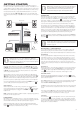
Hardware Overview
610
8 181247 13 1120
21 29 31
9 26 27 35 3732
7 15 14 16 17 19 22 28 33363430
1
2
2324 38 39 4025 25 24
3
43
41
45
48
49
4
42
5
44
46
1
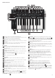
25-note (two octaves) velocity-sensitive keyboard with aftertouch.
2
Pitch and Mod wheels: The Pitch wheel is mechanically biased to return to the centre
position when released. The wheels are internally illuminated.
3
Octave shift keys – transpose the keyboard in octave increments.
4
Transpose - lets you transpose the keyboard in semitone increments, up to a maximum
of +/- 12 semitones.
5
Function/Exit – hold this down to use any of Bass Station II’s On-Key Functions. A
wide range of “system set-up” parameters can be set in this mode.
Master section:
6
LED display – a three-character alphanumeric display showing various items of unit
data – e.g., patch number, octave shift and parameter values – depending on which
other controls are in use.
7
Org. Value – one of these two LEDs will illuminate when the value of a parameter no
longer matches the value stored for the patch.
8
Patch/Value – allows selection of one of the 64 Factory or 64 User Patches, and are
also used to set parameter values for On-Key functions.
9
Save – use in conjunction with Patch keys
8
to save modifi ed Patches in User
Memories.
10
Volume – sets the Bass Station II’s audio volume.
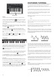
Oscillator section:
11
Osc Select switch – assigns the controls in the Oscillator section to Oscillator 1 or
Oscillator 2.
12
Range – steps through the base pitch ranges of the selected oscillator. For standard
concert pitch (A3 = 440 Hz), set to 8’.
13
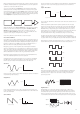
Waveform – steps through the range of available oscillator waveforms – sine,
triangular, sawtooth and pulse.
14
Coarse – adjusts the pitch of the selected oscillator over a range of ±1 octave.
15
Fine – adjusts the oscillator pitch over a range of ±100 cents (±1 semitone).
16
Mod Env depth – controls the degree by which the oscillator pitch changes as a
result of modulation by Envelope 2; the control is ‘centre-off’, so that either pitch increases
or decreases can be obtained.
17
LFO 1 depth – controls the degree by which the oscillator pitch changes as a result of
modulation by LFO 1.
18
Pulse width modulation source – active only when Waveform
13
is set to Pulse; this
switch selects the method of varying the width of the pulse waveform. The options are:
modulation by Envelope 2 (Mod Env), modulation by LFO 2 (LFO 2) or manual control by
the Pulse Width control
19
.
19
Pulse Width – a multi-functional control adjusting the pulse waveform; only active
when Waveform
13
is set to Pulse. When the pulse width source modulation switch
18
is set to Manual, the control adjusts the pulse width directly; when set to Mod Env or LFO
2, it acts as a Modulation Depth control. Note that the pulse width may be modulated by all
three sources simultaneously, by differing amounts.
20
Sync 1-2 – this LED illuminates when the Osc 1/Osc 2 Sync function is enabled (an
On-Key Function)
21
Octave – sets the range of the sub-octave oscillator; the actual pitch of this oscillator
is determined by OSC 1’s pitch, and adds additional bass frequencies (LF) to the sound. -1
adds LF one octave below OSC 1, -2 adds LF two octaves below.
22
Sub Osc Wave – a choice of three waveforms is available for the sub-octave oscillator:
sine, narrow pulse or square.
LFO section:
23
LFO Delay/Speed – the two rotary controls in the LFO section are dual-function,
the function being set by this switch. In Speed mode, the rotary controls adjust the
frequencies of the two LFOs. In Delay mode, they set the “fade-in” time for the LFO.
Speed mode can be changed to Sync mode by using one of the On-key functions. See “
Mod Wh: Filter Freq (bottom C)” on page 17 for further information.
24
LFO waveform – these buttons step through the available waveforms for each LFO
independently: triangle, sawtooth, square, sample and hold. The associated LEDs give a
visual indication of the LFO speed and waveform.
25
LFO rotary controls – these two controls either adjust LFO speed or delay, as set by
the LFO Delay/Speed switch [23].
Mixer section:
26
OSC 1 – adjusts the proportion of Oscillator 1’s signal making up the sound.
27
OSC 2 – adjusts the proportion of Oscillator 2’s signal making up the sound.
28
Sub – adjusts the proportion of the sub-octave oscillator making up the sound.
Additional inputs - up to three further sources may contribute to the synth output; this
control sets their levels. The control’s function is set by switch
30
.
29
Noise/Ring/Ext – determines the function of rotary control
29
. When set to Noise,
the rotary control sets the amount of white noise added to the sound; when set to Ring, it
sets the amount of the output from the Ring Modulator circuit is added (the inputs to the
Ring Modulator are Osc 1 and Osc 2); in the Ext position, an external signal connected to
the rear panel connector
6
Ring Modulator are Osc 1 and Osc 2); in the
6
can be mixed in.