
Fridge DW Series Product Manual

the compressor by snapping the cover over the screw head (1).
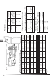
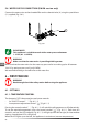
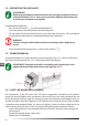
Power supply (g. 5.4.1)
The electronic unit must always be connected directly to the battery poles (2). Connect the
plus to + and the minus to -, otherwise the electronic unit will not work. The electronic unit is
protected against reverse battery connection. For protection of the installation, a fuse (3) must
be tted to the + cable as close to the battery as possible. It is recommended to use 15 A fuses
for 12 V and 7.5 A fuses for 24 V circuits. If a main switch (4) is used, it should be rated to a current
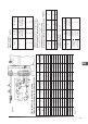
of min. 20 A. The wire dimensions in Fig. 5 must be observed. Avoid extra junctions in the power
supply system to prevent voltage drops from aecting the battery protection setting.
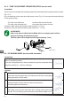
Battery protection (g. 5.4.1)
The compressor is stopped and re-started again according to pre-established voltage limits
measured on the + and - terminals of the electronic unit. The standard settings for 12 V and 24 V
power supply systems appear in g. 5.4.3. Other settings (g. 5.4.4) are optional if a connection
which includes a resistor (9) is established between terminals C and P. In solar applications
without a battery a 220 kW resistor is recommended. In AEO (Adaptive Energy Optimizing)
speed mode the BD compressor will always adapt its speed to the actual cooling demand within
a random operation voltage of 9.6 to 31.5 V.
Thermostat (5.4.1) I
The thermostat (7) must be connected as described in chapter 10.
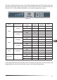
LED (optional, g. 5.4.1)
It is also possible to connect a 10 mA LED diode (6) between the + terminals and D. If the
electronic control unit should detect an operating error, the diode will ash for a certain number
of times. The number of ashes depends on what kind of operational error was recorded. Each
ash will last ¼ second. After the actual number of ashes there will be a delay with no ashes,
so that the sequence for each error recording is repeated every 4 seconds.
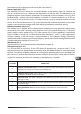
No. FLASHES ERROR TYPE
5
Electronic unit thermal stop. If the cooling system has been overloaded or the ambient
temperature is too high, the control unit will overheat.
4
Insucient motor speed. If the cooling system is overloaded, the motor is no longer able
to maintain a minimum speed of 1,850 rpm
3
Motor start error. The motor is blocked or the dierential pressure of the cooling system
is too high (> 5bar).
2
Fan stop due to overcurrent. The fan has a power input from the electronic control unit
of more than 1App
1 Battery protection stop. The power voltage is outside the set disconnect value.
61
EN