
Service Manual

9LWHOFRP0REL O H7HFKQRORJ\6$ 3URSULHWDU\DQG&RQILGHQWLDO - 15 -
V
V
I
I
T
T
E
E
L
L
C
C
O
O
M
M
M
M
O
O
B
B
I
I
L
L
E
E
T
T
E
E
C
C
H
H
N
N
O
O
L
L
O
O
G
G
Y
Y
S
S
.
.
A
A
.
.
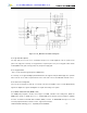
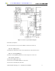
4.2.3 Description of Tx Part Circuit
The 8 bit digital signal fed into TX_BBA(U112) passes through DAC using TXCLK and TXCLK/ as
triggers to produce base band I/Q signal. Inside the MSM(U125), each signal is sent out to the up mixer via
a digital low pass filter. At the mixer, 130.38 MHz I/Q signal obtained by dividing the 260.76MHz VCO
signal by half is used as carrier for the up-conversion of base band signal to Tx IF signal. This signal is
again up-converted into Tx RF frequency signal. The signal converted into Tx RF frequency is amplified at
the drive amplifier. At the Tx AGC AMP, this Tx IF signal level is varied according to the several
parameters defined in mobile station and base station. The proper gain control signal comes out from the
MSM(U125) in the waveform of PDM and rectified to constant DC voltage level by RC low pass filter. The
gain variable range of Tx AGC AMP is 90 dB. The signal is amplified at the power amplifier. Finally, it is
transmitted out to antenna via a duplexer(F100).
TX_BBA (U112)
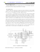
The TX_BBA(U112) Base-band-to-RF Transmit Processor including Tx AGC Amplifier, quadrature
mixers, IF synthesized PLL, RF single sideband up converter, RF driver and Tx IF VCO. It converts a base-
band analog signal coming from a digital base-band processor (Modem chip) to an analog RF signal to be
able to Tx PAM.
The TX_BBA(U112) offers the most advanced and integrated CDMA Tx solution along with minimized
power consumption for extended talk-time performance.
The TX_BBA(U112) connects directly with QUALCOMM’s by the MSM(U125) utilizing an analog base-
band interface. The base-band quadrature signals are up-converted to the cellular band and amplified to
provide signal drive capability to the PAM(U110). The TX_BBA(U112) includes an IF frequency, single
sideband up-conversion from IF to RF, two cellular driver amplifiers, and Tx power control through an 85dB
VGA. TX_BBA(U112) functionality is specifically controlled from the MSM(U125) via the three-line serial
bus interface(SBI).
The Block Diagram of the TX_BBA(U112) is shown in Figure 4.7.
Power Amplifier Module (U110)
The power amplifier Module(PAM,U110) that can be used in the CDMA has linear amplification
capability, whereas in the FM mode, it has a high efficiency. For higher efficiency, it is made up of one
MMIC (Monolithic Microwave Integrated Circuit) for which RF input terminal and internal interface circuit
are integrated onto one IC after going through the GaAs HBT (heterojunction bipolar transistor) process.
The PAM(U110) is made up of an output end interface circuit including this MMIC. The RF transmit
signals that have been amplified through the PAM(U110) are sent to the duplexer(F100).