
Service Manual

9LWHOFRP0REL O H7HFKQRORJ\6$ 3URSULHWDU\DQG&RQILGHQWLDO - 14 -
V
V
I
I
T
T
E
E
L
L
C
C
O
O
M
M
M
M
O
O
B
B
I
I
L
L
E
E
T
T
E
E
C
C
H
H
N
N
O
O
L
L
O
O
G
G
Y
Y
S
S
.
.
A
A
.
.
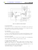
Rx IF SAWFilter (U108)
The Rx IF SAW filter(U108) protects its following stages from close-in Inter Modulation (IM) signals,
provides adjacent channel selectivity, and attenuates the second image.
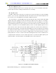
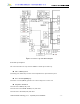
RX_BBA (U109)
Rx_BBA is divided three main parts, IF frequency processing, base-band processing, and digital
interface. It is a receiver IC, installed with a Rx AGC, base-band converter, base-band analog filter, and
A-D converter. It can send a digital base-band signal to digital base-band IC.
The circuit functions of the RX_BBA(U109) include Rx Automatic Gain Controller (AGC) with 90dB
dynamic range input, quadrature IF mixers and Analog to Digital Converters (ADC) for converting to
digital base-band. The RX_BBA(U109) includes clock generators that drive the digital processor and the
VCO(U109) which generates the IF LO frequency for base-band down-conversion. The Rx AGC either
amplifies or attenuates the received CDMA IF signal to provide a constant-amplitude signal to the I/Q
down converter. The IF output of the Rx AGC amplifier separates into I-channel and Q-channel base-
band components and down- converted by mixer with quadrature LO. Rx IF LO signals are generated by
the Voltage Controlled Oscillator of Rx IF. Frequency is stabilized by external varactor-tuned resonant
tank circuit. The I/Q down converter outputs the CDMA signals at base-band frequency. Low-pass
filtering enables the receiver to select the desired base-band signals from the effects of unwanted noise
or adjacent-channel interference. I/Q base band components are converted to digital signals by two
identical 4-bit ADCs. The Block Diagram of the RX_BBA(U109) is shown in Figure 4.6.
Figure 4.6 RX_BBA Functional Block Diagram