
Service Manual


9LWHOFRP0REL O H7HFKQRORJ\6$ 3URSULHWDU\DQG&RQILGHQWLDO - 10 -
V
V
I
I
T
T
E
E
L
L
C
C
O
O
M
M
M
M
O
O
B
B
I
I
L
L
E
E
T
T
E
E
C
C
H
H
N
N
O
O
L
L
O
O
G
G
Y
Y
S
S
.
.
A
A
.
.
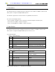
4. Technical Description
4.1 Overview
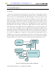
This product consists with 3 parts, which are RF, logic, and UI interface. The block diagram is shown in
Figure 4.1. This product employs the Super-Heterodyne method for wireless communication and the Tx
and Rx frequencies are 824.04~848.97MHz and 869.04~893.9MHz respectively. RF signals received
through the antenna are fed into the low noise amplifier (Receiver MMIC/ LNA, U106) through the duplexer
(F100). Then, they are combined with the signals of local oscillator (VCO, U102) at the down conversion
mixer (Receiver MMIC, U106) in order to create the intermediate frequency (IF). The IF signal is fed into
RX_BBA(U109) through band-pass filter (BPF, U108),. In RX_BBA(U109), the IF signal is changed into
base-band signal. Then, this signal is changed into the digital signal by the analog to digital converter
(ADC, A/D Converter), and the digital circuit part of the MSM(U125) processes the data from ADC. In the
case of transmission, The TX_BBA(U112) receives digital signal from the MSM(U125). In MSM(U125), the
digital signal is changed into analog signal by the digital to analog converter (DAC, D/A Converter), and
then the quadrature signals of base-band are up-converted to the IF frequency bands in TX_BBA(U112).
The Tx AGC in TX_BBA(U112) is designed to be gain-controlled from 85dB dynamic range. In
TX_BBA(U112), the Tx IF frequency mixed with RF local frequency is created Tx RF frequency. After that,
the Power amplifier module(U110) amplifies the RF signal in order to have enough power for radiation.
Finally, the RF signal is sent out to the cell site via the antenna after going through the duplexer (F110).
RF
Sub System
RX_BBA
Baseband-IF
Converter
Memory and UI
Mobile Station Modem
Camera
TX_BBA
Baseband-IF
Converter
LCD
MIDI
RF
Sub System
RX_BBA
Baseband-IF
Converter
Memory and UI
Mobile Station Modem
Camera
TX_BBA
Baseband-IF
Converter
LCD
MIDI
Figure 4.1 Typical Subscriber Unit Block Diagram