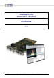
HDM850/850+/950 BROADCAST DECODER USER GUIDE V2.6 CONFIDENTIAL – This document is property of VITEC MULTIMEDIA, and may not be used or diffused to a third party without prior written approval. LW Player User Guide v2.
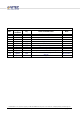
Revision List By Detail of modification Date 1.5 1.6 1.7 1.8 1.9 2.0 2.1 2.2 2.3 2.4 Pages modified All All 15,20 All Update All Update Update Update Update VSH/RBE RBE VSH RBE VSH RBE RBE RBE RBE VSH 12/28/2010 12/29/2010 12/30/2010 12/30/2010 08/05/2011 08/11/2011 08/18/2011 08/22/2011 06/01/2012 11/09/2012 2.5 Update VSH 2.
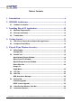
Table of Contents 1. Introduction .......................................................................................... 6 2. HDM850 Architecture .......................................................................... 6 2.1. Hardware installation ........................................................................................ 7 3. Installing PlayerLW Application....................................................... 10 3.1. Minimum Requirements ..............................................
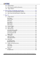
5.8. Playlist Window ............................................................................................... 34 5.9. Entry Properties and Entry Parameters ......................................................... 36 5.10. Output Window............................................................................................... 38 6. PlayerLW(m) Customizing the Interface.......................................... 39 6.1. Moving and resizing PlayerLW(m) windows. .....................................
Set Up SDI Synchronisation ............................................................................ 48 Check Genlock Status ...................................................................................... 48 8. Command Line ................................................................................... 50 8.1. Run Player in Command Line ......................................................................... 50 9. HDM850 Configuration (LW Setting Page) .....................................
1. INTRODUCTION The document describes the use of the HDM850/950 MPEG-2 SD HD / H.264 /H.265 Broadcast Decoder board. Especially, it details the installation process as well as the LW Player software (developed on proprietary Livewire SDK). This powerful decoding application provides a ready to use tool for an easy access to the main features of the board. For integrators, HDM850/950 can be controlled via two different SDK: 2.
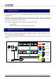
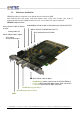
2.1. Hardware installation HDM850 product is composed of one hybrid decoder card and its SDK. Each card has their own sticker with serial number, name of the card, revision, year, week of production and an index. HDM850 card works in 4, 8 or 16 lanes PCI express connector.
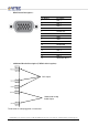
- - DB15-Pinout Description : Pin Number Description 1 AES 1 2 AES 3 3 AES 5 4 AES 7 5 SD SDI OUT 6 GND 7 GND 8 GND 9 GND 10 RESERVED 11 AES 2 12 AES 4 13 AES 6 14 AES 8 15 GENLOCK INPUT Additional Bracket Description (VML02 cable in option): YUV Output Unbalanced Analog Audio Output This bracket must be plugged on J4 connector. CONFIDENTIAL – This document is property of VITEC MULTIMEDIA, and may not be used or diffused to a third party without prior written approval.
Note: Upon request, pinout of the other connectors can be provided. Hardware Instructions: 1 – Shutdown the computer. 2 – Make sure power is off and remove the AC power cable. 3 – HDM850 card is ESD sensitive so pay attention while handling it. Electrostatic Discharge (ESD) can quickly and easily damage or destroy the card or computer.
3. INSTALLING PLAYERLW APPLICATION 3.1. Minimum Requirements MPEG2/AVC Intel Pentium Dual Core 2.5GHz or equivalent processor Microsoft Windows 8 / 7 / XP / 2000 or Windows Server 2003/2008/2012, 32/64bits. 2GB of RAM 7200 RPM SATA2 HEVC Intel Pentium Quad Core 2.8GHz or equivalent processor Microsoft Windows 8 / 7 or Windows Server 2008/2012, 32/64bits. 4GB DDR-III 1666 RAM 7200 RPM SATA2 3.2. Software Installation 1) Run Install.cmd (or install_x64.
If.NET Framework 2.0 (or later version) has been already installed on the system then the warning window appears. In this case, press OK and check the service must be enabled. NET Framework 2.0 has not been able to install since Windows 7. Nevertheless Windows 7/8 suggests user to download and install the newest version of the framework. Connect the PC to Internet in order to get the framework installed on the system. 4) Install StradisSDK. Press «y».
3.3. Troubleshoot The installation result of the software package appears in the DOS window. Please check if the status SUCCEEDED. If a FAIL message appears, here are some known possible causes: 1) DLL installation FAIL: If there were all the statuses FAIL, check user access settings. The installer.cmd must be ran as administrator. Check UAC settings for the user try disabling UAC. If there are livewire.dll, LiveWireVBShell.dll, AssemblyServer.
3) The board does not appear in the Device Manager. Try to reinstall the driver. If the board still not appears, check for the LED on the board. A correct detection of the board is indicated when the LEDs are flashing one after the other. If the LEDS are not flashing, please contact VITEC Technical Support. 4. GETTING STARTED. 4.1. Overview of PlayerLW and PlayerLWm applications PlayerLW and PlayerLWm allow you to manage and control HDM850 and HDM950 boards.
- Click [PlayerLW Configuration] (page 15). - Choose [Open Configuration…] in the [PlayerLW Configuration]. Select the copy of active profile. Choosing an Active Profile the board, which number is set in the active profile, runs. Open [Board Selection] (page 17 (16)) to find out which board has been ran (page 20). Select one of [NOT USED] boards from the list if you need to start the other board with the active profile. Current board will be released and get status [NOT USED].
5. PLAYERLW(M) WINDOW OVERVIEW 5.1. Main window Configuration 1. 2. 3. PLAYERLW CONFIGURATION Open menu to load, edit and close XML configuration file. Double click on the button closes selected Active Profile. Selected ActiveProfile (configuration) is marked in bold. QUICK ACCESS TOOLBAR The toolbar shows the most useful buttons. SETTINGS Click the down row button to expand the list of Quck Access settings and compose custom Quick Access Toolbar.
5.2. Decode Tab Decode Tab contains main Playback control toolbars and the most useful Device settings, which also are available from [PlayerLW configuration] menu. ADD ENTRY (FILE) Click Add “plus” button to open standard Windows dialog and choose files from Disk or Network storage. ADD ENTRY Opens menu with additional possible types of entries: Network Stream, Virtual I-Frame, SDIIN Insertion. REMOVE ENTRY Select an entry in the Playlist Window and click Remove to delete the entry from the playlist.
ENABLE Activates video preview window. DISABLE Deactivates the video preview window. AUTOSTART If Autostart is enabled then PlayerLW activates the Video Preview as soon as HDM950/850 starts decoding. It deactivates Video Preview when the playback is stopped. PREVIOUS FILE Force Switch to previous file in the playlist. NEXT FILE Force switch to next file in the playlist. OUTPUT Specify the output resolution and fps on HD-SDI output. SELECT BOARD Opens [BOARD SELECTION] menu.
Open Network Stream Window PROTOCOL Choose one of the following protocols: UDP, RTP or RTSP. ADDRESS Local host – is a default value. It sets the receiver address. The value mustn’t be changed. PORT Specifies the port of network transmission. STREAM The edit field activates when RTSP is ON. Write down source address in the field. SAVE INCOMING STREAM TO FILE Enables writing incoming stream to storage. FILE NAME TO SAVE STREAM Choose a directory and name to save the stream.
Open Virtual File Window STANDARD Virtual file must coincide with video output standard of the device. Choose a standard with _df at the end to provide drop frame correction. DURATION Virtual file duration is specified in frames. So 1 sec of NTSC is 30 frames, PAL – 25 frames. Open SDI-Input Insertion Window DURATION The SDI input insertion is specified in milliseconds. Set Duration and press OK button to add the entry to the playlist.
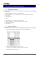
Board Selection Board Selection Menu shows list of all the installed boards in the system. And allows user to choose the board for the desired Active Profile, which has been selected before opening the Board Selection window. NO SELECTED BOARD Choose the values from the list if the application must be started without a board. Or choose the value if all the board have been already busied and the menu needs to be closed. BOARDS IN THE SYSTEM This is the list of boards that have been installed in the system.
Groups Use Groups menu to join the boards in groups in order to synchronize their functionality. The boards in a group can Start/Pause/Stop synchronously. LIST OF OPEN BOARDS&PROFILES The list shows all ran Active Profiles in the PlayerLWm. ACTIVE PROFILE NAME The field represents Active Profile’s file name that has been loaded to configure the environment of the board. BOARD PROPERTIES The field represents #Board Number in the System, Type of the Board, Serial Number and current status.
Audio Matrix Audio Matrix is a visual representation of the LW Setting Page/Device/Embedded SDI, AES|EBU Audio Output, LW Setting Page/Device/Primary | Secondary Channels – HDMI Output, LW Setting Page/Device/Analog Audio Output. SDI-IN MATRIX MODE Specifies the mode of SDI-IN MATRIX patch. LINEAR patches input and output with the same channel number. ZERO bypasses all the inputs. CUSTOM displays that a value has been changed in the SDI-IN Matrix. SAME AS PCI-E MATRIX copies PCI-E Matrix settings.
PCI-E AUDIO INPUT These bar graphs indicate the send level of the signals sent from PCI-E (decoded file’s audio tracks) to output bus. Drag a bar graph to the left to set the minimum value ( -∞ dB ) Drag a bar graph to the right to set the maximum value ( +24.1 dB ) SDI-IN EMBEDDED AUDIO These bar graphs indicate the send level of the signals sent from SDI-IN to output bus. Drag a bar graph to the left to set the minimum value ( -∞ dB ) Drag a bar graph to the right to set the maximum value ( +24.
5.3. VTR Tab ENABLE VTR Selects PlaybackController+Queue+VgaMon Assembly and starts indexing the files from playlist if the files haven’t been indexed. Sets the first frame of the first file in the playlist in CUE. ENABLE RS422 INPUT Selects RS422+PlaybackController+Queue+VgaMon Assembly. It allows using an RS422 control connected to J7 socket via SAC014. PREVIOUS FRAME Displays previous frame in the file.
Sets and displays the next frame in the file. If the function is implemented to the last frame of the file, it sets and displays the first frame of next file. NEXT FILE Sets and displays the first frame of the next file. GO TO ENDING Sets and displays the last frame of the last file in the playlist. GO TO ENDING EXPAND Sets and displays the I-Frame of the following GOP in the file. It sets and displays the first I-Frame of next file if the function is implemented to a frame in the last GOP of the file.
FAST REVERSE (REWIND) Does rewind with 2x speed. REVERSE PLAY Does backward playback with 1x speed. SLOW REVERSE Does backward playback with a half speed. SLOW REVERSE 1/2, 1/3, 1/5, 1/10, 1/20. Expand and choose the backward playback speed. FAST REVERSE (REWIND) 2x, 3x, 5x, 10x, 20x, 50x Expand and choose the rewind speed. PAUSE Pauses playing back. FAST FORWARD Does forward playback with 2x speed. FORWARD PLAY Does playback with normal speed. SLOW FORWARD Does forward playback with a half speed.
5.4. OSD Tab Use OSD Tab to type text OSD, load Image OSD, load Animation OSD and numerate output video by TimeCode OSD or Frame Number OSD. OSD applies only to Primary Output. ON/OFF On/Off checkbox enables/disables OSD on the board. ANIMATION MANAGER The check box opens OSD Manager. RESET Removes all the previously loaded OSDs. X/Y: Sets OSD position. X/Y coordinates. The position counts from the upper left corner. A: Sets the OSD transparency of a picture or a text. 255 – opaque OSD.
OSD Animations Manager FRAME COUNT Sets the number of frames in animation sequence that is going to be created. X-POSITION Sets horizontal position of an animation sequence. Y-POSITION Sets vertical position of an animation sequence. CREATE ANIMATION After specifying [Frames Count], [X,Y-positions] press the button to display Open dialog in order to select pictures for the animation sequence. If you select more number of pictures than it has been specified in [Frames Count], PlayerLW(m) rejects overhead.
REMOVE Remove the selected item from the list. START Select an Item from the list and press START to display the OSD. PAUSE Select an Item from the list and press PAUSE to freeze the OSD animation. STOP Select an Item from the list and press STOP to stop and hide the OSD from the Display. MOVABLE Makes the Frame Counter move around the previously set X,Y-position. This mode is used as a demo to show move functionality. CREATE Creates a Frame Counter OSD Animation Item.
5.5. Setting Tab CALCULATE DURATION Calculates duration of the playlist. It’s not recommended to activate this setting during playback if the playlist consists of many entries. Calculation process requires some CPU and may lead to dropping of frames. PLAYLIST Show/Hide the Playlist window. ENTRY PROPERTIES Show/Hide Entry Properties window. ENTRY PARAMETERS Show/Hide Entry Parameters window. INFORMATION Show/Hide Information window. OUTPUT Show/Hide Output window. STATUS BAR Show/Hide Status Bar.
Firmware Upgrade CURRENT BOARD PlayerLW(m) application reads firmware version from the board and displays it in the menu. PREFERED The version, which is included into the distribution pack. PREFERRED/CUSTOM Preferred is a default option. This option is recommended to upgrade the board. Check or upgrade the firmware version. Custom option allows user to select a firmware bit stream from disk.
HEVC Licence Upgrade HEVC H.265 is High Efficiency Video Coding standard. HDM850+/950 can decode H.265 streams up to 1920x1080p60. SERIAL NUMBER This field displays type and serial number of the board that will be upgraded to decode H.265. If there are several HDM850 boards in the system, every board, which have to decode H.265, needs upgrading. COMPANY/NAME Write down your company name for identification in VITEC support database.
5.6. Video Preview Window, Seek Bar CONFIGURATON NAME Configuration name consist of XML configuration file’s name, board number in the system, board type, board Serial Number, and group number if the board is grouped. PREVIEW WINDOW Video Preview window is used for monitoring of the output video, status information, overlays and OSD of the current board. CONFIGURATION LIST Shows the list of the configurations that run in PlayerLWm.
5.7. Information Window The window shows time information of the current playlist and played file. PLYLIST DURATION Shows total duration of the playlist. It doesn’t factor in Network Stream Insertion and/or elementary stream files duration. Turns on [CALCULATE DURATION] on the Settings Tab to sum durations of entries in the playlist. CURRENT TIME Displays current time of the decoded frame in the file (entry). You don’t have to turn on Calculate duration to watch current time.
MOVE AN ENTRY IN PLAYLIST Select a file, press and hold SHIFT and move selected file by mouse to change the order or move the file in playlist. MOUSE CLICK ON AN ENTRY One click selects an entry. Double click starts decoding the entry. CONFIDENTIAL – This document is property of VITEC MULTIMEDIA, and may not be used or diffused to a third party without prior written approval. LW Player User Guide v2.
5.9. Entry Properties and Entry Parameters Entry Properties and Entry Parameters windows show information and playback settings of selected entry. ENABLE/DISABLE/ADD/REMOVE A STREAM Use the group of the buttons to create an entry. From left to right: Select an audio stream and enable the audio stream that is already in the list. Select an audio stream and disable the audio stream that is already in the list. Select Main File in the top of the list and add a new stream from a file.
DISPLAY NAME Specifies the files name in the playlist. The parameter copies the file’s name with path by default. It’s changeable parameter. To change the value set focus in the value field and write down custom value. Playlist widow shows new name as soon as you press enter. INITIAL POSITION This parameter can be applied to an entry that type is a video file. It sets start position in bytes. Player starts decoding from the I-frame of the GOP next to the position.
5.10. Output Window A log window which provides status information of the board. The window shows status of the board warnings and errors. The messages help to find out configuration issues and tune the system. CONFIDENTIAL – This document is property of VITEC MULTIMEDIA, and may not be used or diffused to a third party without prior written approval. LW Player User Guide v2.
6. PLAYERLW(M) CUSTOMIZING THE INTERFACE 6.1. Moving and resizing PlayerLW(m) windows. Playlist window, Playlist entry properties and Output windows can be individually moved and resized. The ActiveProfile window (Video Preview window) can be resized. Drag the border in the desired direction to resize the appropriate window. The windows on either side of the border are resized accordingly. Any border between two windows in PlayerLW can be dragged.
6.2. Show several Preview Windows in PlayerLWm In multi-board configuration, when two or more than two HDM850/950 are used, the profiles for each board in one PlayerLWm application can be opened with a separate preview window. By default, PlayerLWm shows only one preview window. The second profile is hidden. And only clicking on the profile’s tag you can see the preview window of its profile.
7. HOW TO… 7.1. Compile Playlist Entry Types VIDEO AUDIO FILE PlayerLW decodes both muxed video and elementary video streams. It supports MPEG2, AVC, HEVC video stream. PCM, MPEG Layer II, AAC audio stream. Ts, Ps, MXF, mp4, mov containers. PICTURE PlayerLW supports BMP MS 24-bit file format. - Press [ADD ENTRY] to open explorer window. - Select a bmp file and press [OPEN] in the dialog. The picture will be added at the end of playlist. - Open [Entry Properties] and set Duration for the entry.
SDI-INSERTION The entry is used to do video/audio insertion from SDI-Input. - Press ADD ENTRY button in the Decode Tab. - Choose SDI-INSERTION from the appeared list. - In the SDI-Insertion Menu set duration in milliseconds. Zero value means infinite SDIInsertion playback. Create Playlist At the first start PlayerLW shows empty playlist window. There are four ways how to add an entry to the playlist: - Press Add Entry button in the Decode Tab and choose an entry.
- Playlist that is created in a text editor and saved as .lst. This playlist can consist of full name of files. Playlist that is created and saved by PlayerLW as .xml. This type of playlist contains extra information: preview name, duration, number of video and audio streams. There are two ways of loading a playlist: - Replace by new. When the playlist is selected, a confirmation message appears on the screen. Press “YES” if you need to replace old playlist.
Autostart doesn’t work in Trick Mode. 7.3. Device Toolbar Output: Specifies the output resolution and fps on HD-SDI output. In fixed mode, when one of the available modes is selected, HDM board up scales or downscales resolution of files that have different resolution to output in order to get full screen picture.
- Enable [Animations Manager] checkbox. Set Frame Count value. Set X-position and Y-position. Click [Create Animation]. A new string appears in the animation list. Click [Set Frames] Choose bmp or tga pictures for the animation. The number of chosen pictures in the dialog must coincide to the previously set Frame Count value. Click open in the dialog. Remove OSD - Enable [Animations Manager] checkbox. Select the animation from the list. Press [Remove] 7.5.
7.6. Multi-board Set Up Multi-board 1. Create copy of ActiveProfile.xml for every board in the system. 2. Run PlayerLWm 3. Click on [PLAYER CONFIGUTATION] button (page 15). 4. Choose [Open Configuration] 5. Select a copy of ActiveProfile.xml 6. Open Board Selection menu. Click on [SELECT BOARD] in Device Tab (page 20). 7. Choose a board with [NOT USED] status. 8. Close Board Selection Menu. As the result the board will be linked to the profile. Repeat steps 3-8 for every other board that needs to be run.
7.7. Groups and Synchronisation Join Group The boards, which are opened in PlayerLWm or separate PlayerLW applications, can be groped in order to start decoding synchronously. - Open Group menu clicking on [GROUP] button in Decoder Tab (page 21). - In the menu click in the Group column opposite of the board which has to be added to the group (page 21 (4)). The list of groups appears. - Choose the number of group for the board. - Repeat previous step for others boards. - Close the menu.
7.8. Genlock Set Up Genlock - Plug SAC012 cable to the middle pins of J4 connector on the master board. The middle pins provide Y-component signal, which can be used for genlocking of a slave board. Plug the cable to J1 connector of the slave board. If there is a next slave board use JP2 connector of the genlocked board to pass through the genlock signal. Plug a 75Ohm terminator to JP2 of the last board in the chain. Open PlayerLWm application. Select configuration of the slave board.
- - - Open configuration file of the board (ActiveProfile.
8. COMMAND LINE 8.1. Run Player in Command Line Help: PlayerLW.exe –help displays the above window. Example of start One board with a playlist and auto start decoding. PlayerLW.exe –profile “path\ActiveProfile.xml” –list “path\playlist.xml” -play Example of start One board with a file and auto start decoding. PlayerLW.exe –profile “path\ActiveProfile.xml” –file “path\media.ts” –play Use coma between file names to run player with more than one file.
9. HDM850 CONFIGURATION (LW SETTING PAGE) Properties of a component, used in different assemblies, are common for all assemblies, which use this component. Example: Change “Repeat List” parameter in Queue manager component, then go to another Assembly. The “Repeat List” is also changed in another Assembly. 9.1. Queue+Device+VgaMon Assembly Queue Manager Repeat List: To loop the playlist. Send end of queue: - ALWAYS – stops player when reaching the end of playlist.
Device Current Board : Default value: 1 Number of board currently used in the PC system 0: No HDM850 board in system. If there are more than one board in a system, individual ActiveProfile.xml must be created for every board. “Current Board” setting must be set to 1 in ActiveProfile1.xml (for the first board) and 2 in ActiveProfile2.xml (for the second board) etc. Field Display Mode: Choose the type of conversion when playing back of interlaced video files in to progressive video output does.
o Only second field display: Duplicates even lines Play First Video Frame in Pause: Default Value is “ON”. - ON - Player updates frame on seeking. - OFF - Player holds one frame, which was got on PAUSE, while seeking. Paused frame is held until press Play/Resume. In trick mode assembly (Playback control assembly) this parameter always forced “ON”. Play Audio for First Video Frame in Pause: - ON – HDM board plays a bit of audio, which belongs to seeked frame, when seek to a frame happens.
Allows shifting picture by the value to conform to different NTSC’s Standard. (CEA-861D specifies lines 22–261 and 285–524 for active video. IEC 61834-2, ITU-R BT.1618, and SMPTE 314M (DV formats) specify lines 23–262 and 285–524 for active video. ITU-R BT.656 specifies lines 20–263 and 283–525 for active video, resulting in 487 total active lines per frame.) Disable Clipping of SDI Value: Enable/Disable PLUGE Pattern for testing of SDI input.
- Crop to Output: cut 16x9 picture from left and right sides to show it in 4x3 aspect ratio. Cut top and bottom lines of 4x3 picture to shows it in 16x9 aspect ratio. - Add Pillar/Letter Boxes: add (black vertical) pillar-boxes to 4x3 picture to transform into 16x9 picture. Add (black horizontal) letterboxes to 16x9 picture to transform into 4x3 picture. Audio embedded group: Specify the number of audio channels used on the Primary channel.
Timecode Mode: Available modes: - None: Time code transmission is turned off. - WF VITC: SMPTE12 Vertical Interval Time Code transmitted as Wave Form. This mode can only be used for PAL/NTSC output modes. - ATC VITC: SMPTE12 Vertical Interval Time Code carried in the Ancillary Data Space. - ATC LTC: SMPTE12 Linear Time Code carried in the Ancillary Data Space. - ATC VITC & LTC: This mode allows simultaneous transmitting of both types of time code.
WSS (AFD) Mode: Available modes: - WSS (Wide Screen Signaling) Waveform: provide aspect ratio data in PAL/NTSC - AFD Ancillary packet: Provide aspect ratio data in HD - WSS+AFD: Player automatically selects which mode should be used. WSS for SD, AFD for HD. WF TC First Line insertion: Specify the first line of waveform time code. (Default 14) WF TC Second Line insertion: Specify the second line of waveform time code.
Embedded SDI, AES|EBU Audio Output There is 32x16 audio matrix to route the audio input channels to the AES3 audio outputs. AES3 PCM Mode: Available modes: - Consimer - Pro AES3 NonPCM Mode: Available modes: - IEC 61937 - SMPTE337M Output Audio Channels 01-16: Audio Input Channel from the Decoder or from SDI-Input can be routed to AES3 output channel or group of channels.
- Click right button on the desired channel and select Hidden to hide the Audio Input Channel, then fold/expand “Output Audio Channel ##”. Once hide, it is possible to show the channel through the LW Setting Page/View/Show Hidden or press Alt+S. - Click right button to lock the value of the parameter right click on the desired channel and select Read Only. DCA (Digital Control Amplifier): This parameter modifies the value of the group of Input Channels.
- Click right button to lock the value of the parameter right click on the desired channel and select Read Only. DCA (Digital Control Amplifier): This parameter modifies the value of the group of Input Channels. Primary|Secondary Channel – Component Output Channel: - HD-Primary channel: In this case, Component Output is routed on the Primary HD-SDI channel. The HDMI video resolution/frame rates remains identical to the Primary HD-SDI Channel Output (please refer to the diagram on page 4).
Secondary Channel – SD-SDI Output Use HD out resolution: This parameter defines the relationship between the Primary HD Channel and the Secondary SD Channel. When ON and when the Primary Channel Output frame rate is set to 29,97; 30; 59,94; 60 fps, then the Secondary Channel Output resolution is automatically set NTSC. When ON and when the Primary Channel Output frame rate is set on 25; 50 fps, then Secondary Channel Output resolution is automatically set PAL.
By default, space color conversion between SD/HD is automatic (Input/Out Color Mode selection) Input Color Mode: The HDM 850 supports SD (601) and HD (709) input color spaces range Output Color Mode: The HDM 850 provides SD and HD output color spaces range Here are the color parameters that can be adjusted: Gain: Min 0, Max 200, Default 100 Brightness: Min -100, Max 100, Default 0 Saturation: Min 0, Max 200, Default 100 Gamma: Min 0, Max 1024, Default 512 Hue: Min -180, Max 180, Default 0 V
WSS (Wide Screen Signalling) Waveform: provide aspect ratio data in PAL/NTSC WF TC First Line insertion: Specify the first line of waveform time code. (Default 14) WF TC Second Line insertion: Specify the second line of waveform time code. (Default 16) WF Closed Caption Line insertion: Specify the line of EIA608 waveform closed captioning. (Default 21) Enable RDD11 rendering: Activate RDD11 data rendering form an entry file.
To retrieve the Analog Audio, use the BNC connectors (Left out, Right out) or J3 pins on the board (Audio Out). The Default value (255) provides audio without volume modification. Lock Tracks: When ON the value of both channels (L/R) is linked. If Volume Left is modified then Volume Right is modified too automatically. Mute Output: Mute the Analog Audio output. Left/Right output audio channel: Use these parameters to route the audio inputs to the Analog Audio Output.
9.2. RS422+PlaybackController+Queue+VgaMon Assembly To Set RS422+PlaybackController+Queue+VgaMon Assembly 1. Start PlayerLW application. 2. Add a file or group of files to playlist. 3. Open VTR Tab. 4. Check “Enable VTR” box. Checking the box PlayerLW sets “RS422+PlaybackController+Queue+VgaMon” Assembly. Once VTR mode is enabled, the buttons from Playback menu group on Decode Tab (page 16 (7,8,9) ) must not be used to control the playback.
OFF, only PLAY and STOP commands are available from RS-422 controller. To enable the other control commands, “Enable trick mode” must be set to « ON ». Note: To rebuild the index file, change the Index Loading Mode. 2. Resource Usage Ratio: Change this parameter to optimize the processing speed of the RS422 commands. 3. Commands: The following commands are available both on VTR Tab and in LiveWire Setting Page. Play.
RS-422 connection Connect SAC014 cable to the RS-422 pins on the board. There is J7 connector for RS-422 machine control on HDM850. Plug in Stradis SAC014 to J7 connector of HDM850 board. Install the cable with the red (pin 1) line to the right side of the board. Enable the RS422 Controller parameters in LW Setting Page/RS-422 or check RS-422 on the VTR Tab (page 24). For example: 1) Take JLCooper Electronics MCS2 controller (or equivalent). 2) Connect to RS-422 port. 3) Start PlayerLW application.
5) 6) 7) 8) 9) Select an MPEG2/AVC/HEVC file or group of files. Open VTR Tab (page 24). Check Enable VTR box and wait for indexing files (page 24). Check RS-422 box (page 24). Press “Play” button on the MCS2 controller. If the controller connected correctly then number of command (20 01 21 00) appears in the “Output” window of the PlayerLW. After this sequence of directions the PlayerLW plays media file. Press “STOP” button to pause. Press ”Rewind” button to rewind.
10. LIMITED WARRANTY ON HARDWARE PRODUCTS What is covered: Any defect in materials or workmanship. For how long: One year. What we will do: If your VITEC product is defective and returned within one year of the date of purchase, we will repair it or, at our option, replace it at no charge to you. If we repair your VITEC product, we may use new or reconditioned replacement parts. If we choose to replace your VITEC product, we may replace it with a new or reconditioned one of the same or similar design.
God, or use in those countries where such use violates Part 779 of the Export Administration Regulations of the United States Department of Commerce. If your VITEC product is not covered by our warranty, e-mail us at support@stradis.com or call us at +1-404-320-0110 for advice about whether we will repair your VITEC product and for other repair information, including charges.