
User manual

Installation Guide
Harmony 2ES and 4ES 9
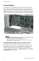
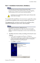
Cable Installation (A/V Breakout)
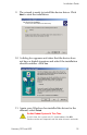
1. Back the set-screws off fully before attaching the cable.
Do Not Use the attaching screws to pull the cable onto the
female D-Sub connector of the board.
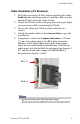
2. Orient the D-Sub on the cable properly and apply slight
even pressure while connecting the D-Sub.
3. Secure the Universal Cable in place with the two
screws.
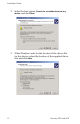
4. Attach the patch cables to the
Universal Cable as per the
installation.
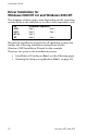
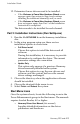
5. If required, connect the
Y-adapter audio cables, (1/8 inch/
3.5 mm stereo phone plug to two RCA plugs), from the
Harmony card’s digital audio output jacks to the proper
inputs on an external audio receiver/decoder. Note that the
audio output jack labeled
CH 1-2 is designated for channels 1
& 2 and the second audio output jack labeled
CH3- 4 is
designated for channels 3 and 4.
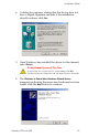
Apply Strain Relief When Attaching Patch Cables
The set-screws will easily support the Universal Cable strain, but will
not take into account the weight and strain of any connected cables.
Ch 1 - 2
Ch 3 - 4