
Service manual


7: Troubleshooting Guide
CHRISTIE INC. CHRISTIE INC. - - 35/70 Service/PM Manual
July, 1997
ELECTRONIC CIRCUIT INFORMATION
This section contains current data for the electronic circuits used in the 35/70 Automated Film Projector. For each circuit,
the following information is included:
• Parts List
• Circuit Diagram (optional)
• Component Layout (optional).
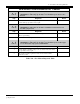
The following circuits are described in this section:
• 0207 Torque Arm Optical Pot Assembly
• 0208 Optical Sensor Assembly
• 0300 Sync Separator
• 1008 Frame Counter Display
• 1034 Power Supply Assembly
• 2262 Bi-Level Interface
• 2267 Keypad
• 2268 Pulldown Sensor
• 2269 Shutter and CV Encoder
• 2273 Pulse Drive Amplifier
• 2275 Pulldown Amplifier
• 2276 Framing Control
• 2293 Central Processing Unit
• 2285 PWM Amplifier
• 5051 70mm BOF/EOF Sensor
• 5052 35mm BOF/EOF Sensor
In addition, miscellaneous diagrams and parts lists that are not necessarily associated with a specific card are grouped at
the end of this chapter:
• 35/70 System Interconnect Diagrams
• Film Velocity Diagram
• 35/70 Timing Diagram
• Master/Slave Interconnect Diagram