
Technical data

10
Chapter 1: DVP Specifications
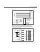
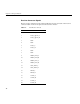
Figure 1-5 DVP Clock and Data Timing
Electromagnetic Interference Precautions
When the external DVP interface cable is not in place, the data drivers are powered down
to save power and minimize EMI interference to other equipment. 5V-PECL signals have
lower emissions than CMOS or TTL signals. Each differential pair in the external cable is
individually shielded with foil. In addition, the entire cable is shielded with a braided
shield. The external shield of the DVP cable must be tied directly to chassis ground on
both the Silicon Graphics logic cabinet and the customer’s chassis.
Site Preparation
Chassis grounds (on the Onyx rack and the customer equipment) should be at the same
potentials, supplied from the same AC mains and ground. PWR_GOOD is likely to be
out of spec if there is much difference in ground potential between the two equipment
chassis, resulting in a shutdown of the DVP interface to prevent equipment damage. (See
“Receiver Power Indicator (PWR_GOOD)” on page 6 for more information.) Both chassis
should be supplied from the same AC electrical source in order to minimize ground
differentials between chassis.
Caution: Any difference in ground potential greater than 500 millivolts (0.5 volts)
between two chassis connected by copper XIO cables can cause severe equipment
damage, and can create hazardous conditions.
ABCD
DVP video data
pixel clk
CLK_2_H
CBLANK_H
CLK_2_QUAD_H
recovered clk
WXYZ
CBLANK leads data by three clocks.